Illumination device
A technology for lighting devices and installation parts, which is applied to lighting devices, lighting device light guides, lighting device components, etc., and can solve the problems of non-adjustable light guide plate posture, invariable light distribution of lighting devices, and inability to adapt to different light distribution requirements. , to achieve the effect of convenient and labor-saving posture adjustment
- Summary
- Abstract
- Description
- Claims
- Application Information
AI Technical Summary
Problems solved by technology
Method used
Image

Examples
no. 1 approach
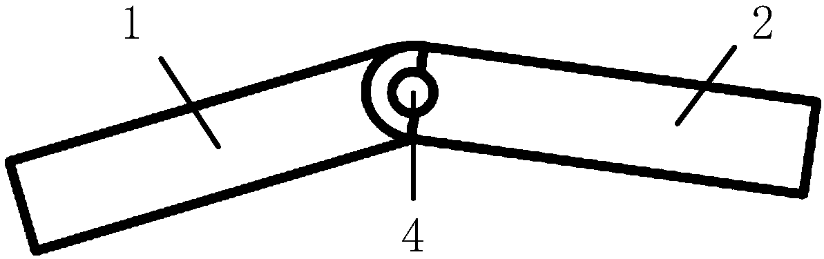
[0036] figure 1 A front view of the first embodiment of the lighting device of the present invention is shown. Such as figure 1 As shown, a rotating assembly 1 is rotationally connected with a fixed assembly 2 through a rotating shaft assembly 4, and a motor drive mechanism (not shown) can drive the rotating shaft assembly 4 (in this embodiment, the rotating shaft assembly 4 only includes one rotating shaft) The rotation further brings the rotating assembly 1 to rotate relative to the fixed assembly 2 . Wherein, the rotating assembly 1 is provided with a light guide plate.
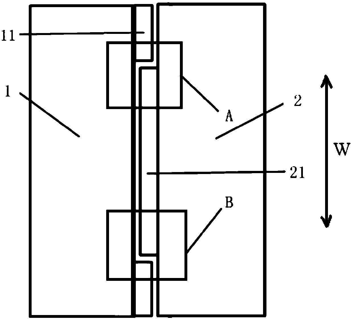
[0037] figure 2 show figure 1 top view. Such as figure 2 As shown, the rotating assembly 1 has a rectangular shape as a whole and the rotating assembly 1 is provided with two first installation parts 11 fixed to the light guide plate, the fixed assembly 2 has a rectangular shape as a whole and the fixed assembly 2 is provided with a mounting part 11 that cooperates with the first installation part ...
no. 2 approach
[0042] Figure 5 A front view of a second embodiment of the lighting device of the present invention is shown. The basic structure of the rotating assembly 1, the fixed assembly 2, the motor drive mechanism (not shown) and the rotating shaft assembly 4 in the lighting device of the second embodiment is the same as that of the rotating assembly 1 and the fixing assembly in the lighting device of the first embodiment. 2. The basic structures of the motor drive mechanism 3 and the rotating shaft assembly 4 are roughly the same. Such as Figure 5 As shown, there are two rotating assemblies 1, and the two rotating assemblies 1 are respectively rotatably connected to the fixed assembly 2 through the rotating shaft assembly 4, and the motor drive mechanism (not shown) can drive the rotating shaft assembly 4 to rotate and then bring the rotating assembly 1 relative Rotate on the fixed component 2.
[0043] Preferably, in this embodiment, the two rotating components 1 are arranged s...
no. 3 approach
[0046] Figure 6 A top view of a third embodiment of the lighting device of the present invention is shown. Such as Figure 6 As shown, the rotating assembly 1 is trapezoidal in shape and there are four in number, and the four rotating assemblies 1 are respectively rotatably connected to the fixed assembly 2 through the rotating shaft assembly 4 (including one rotating shaft in this embodiment). The fixed assembly 2 is circular, and four rotating assemblies 1 are evenly arranged along the circumference of the fixed assembly 2 . A motor driving mechanism (not shown) can drive the rotating shaft assembly 4 and then bring the rotating assembly 1 to rotate relative to the fixed assembly 2 . Wherein, the rotating assembly 1 is provided with a light guide plate.
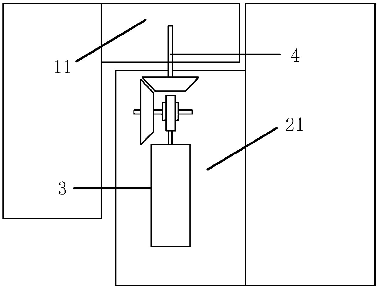
[0047] Figure 7 show Figure 6 The structural diagram of the motor drive mechanism of the lighting device in . Such as Figure 7 As shown, the motor drive mechanism 3 includes a motor 31 and a first transmission ge...
PUM
 Abstract
Description
Claims
Application Information
 - R&D
- Intellectual Property
- Life Sciences
- Materials
- Tech Scout
- Unparalleled Data Quality
- Higher Quality Content
- 60% Fewer Hallucinations
Browse by: Latest US Patents, China's latest patents, Technical Efficacy Thesaurus, Application Domain, Technology Topic, Popular Technical Reports.
© 2025 PatSnap. All rights reserved.Legal|Privacy policy|Modern Slavery Act Transparency Statement|Sitemap|About US| Contact US: help@patsnap.com