
Split type self-protection sealing surface structure of regulating valve

A split-type, self-protecting technology, applied in the valve's device for absorbing fluid energy, sliding valve, valve details, etc., can solve the problem of scouring at the bottom of the valve core, and achieve the effect of convenient disassembly

Pending Publication Date: 2020-02-18
SHANGHAI POWER EQUIP RES INST
View PDF1 Cites 0 Cited by
  • Summary
  • Abstract
  • Description
  • Claims
  • Application Information

AI Technical Summary

Problems solved by technology

[0004] The invention patent of authorized notification number CN 206889687 U discloses a regulating valve with a spool protection device. The regulating valve includes a valve body, a valve seat, a bonnet, a valve stem and a spool. The spool is arranged in the valve body. The lower end of the valve rod extends through the valve cover into the valve body and is connected with the valve core. A valve core protection device is sheathed outside the valve core, and the upper end of the valve core protection device is connected to the upper end of the valve core through a spring. Since the spool protection device is set outside the spool and the upper end is connected to the spool by a spring, it can only protect the side of the spool from fluid erosion, and the bottom of the spool will still be eroded by fluid when the spool is opened.

Method used


Image

  • Split type self-protection sealing surface structure of regulating valve
  • Split type self-protection sealing surface structure of regulating valve
  • Split type self-protection sealing surface structure of regulating valve

Examples


Embodiment

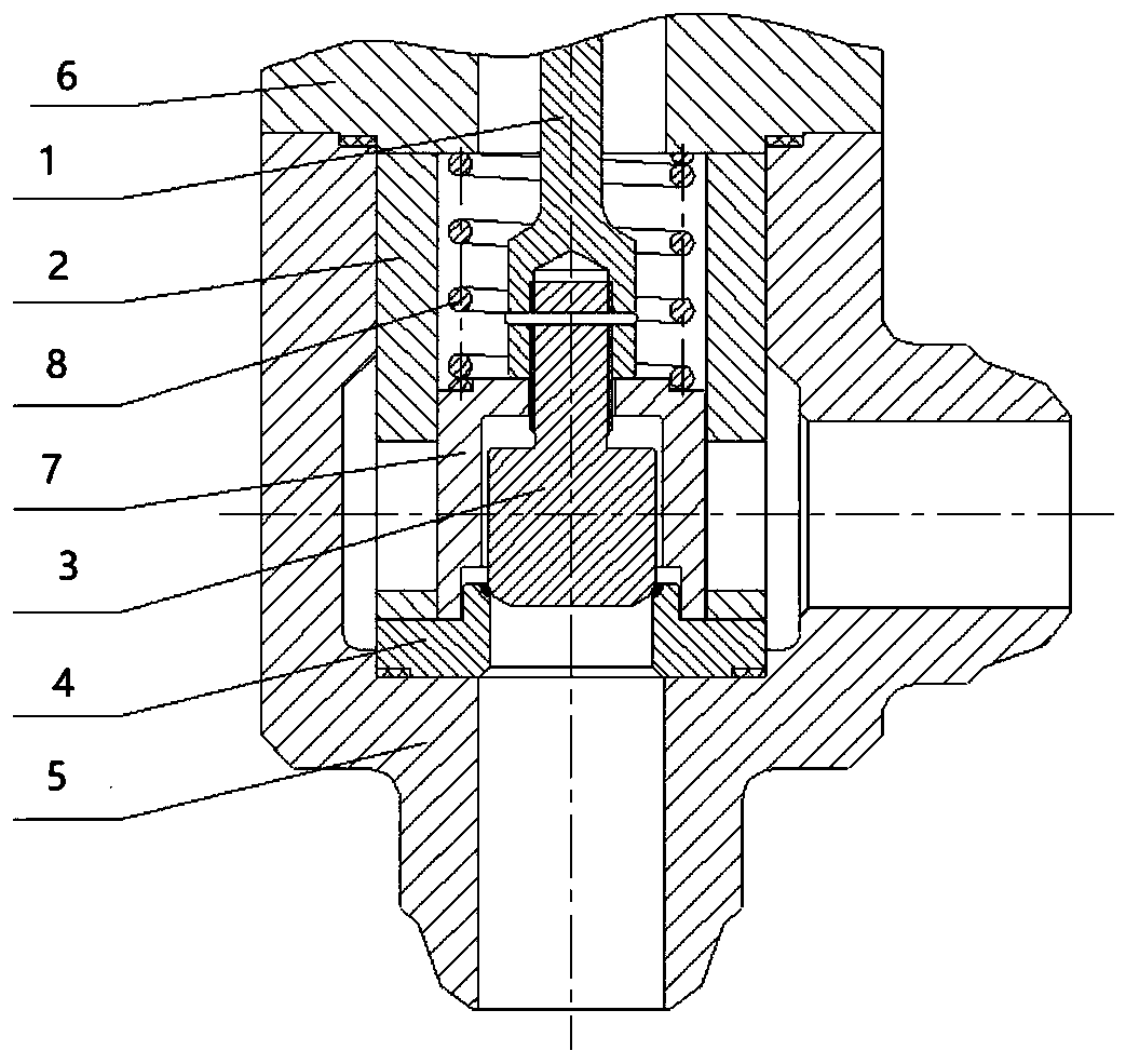
[0017] Such as image 3 As shown, a control valve split self-protection sealing surface structure of the present invention includes a valve stem 1, a sleeve 2, a valve core 3, a valve seat 4, a valve cover 6 and a valve body 5, and the innermost end of the valve body 5 is a valve Seat 4, valve core 3 is located in the valve body 5, the upper part of the valve seat 4, the lower end of the valve stem 1 extends through the valve cover 6 into the valve body 5 and connects with the valve core 3, and the valve core 3 is provided with valve core protection Device 7, a sleeve 2 is provided on the outside of the spool protection device 7, and the key to improving its structural design is that a spool protection device 7 is arranged on the periphery of the spool 3, and the height of the internal space of the spool protection device 7 is greater than the height of the spool 3, The spool 3 is allowed to move up and down in the spool protection device 7, the spool protection device 7 is co...


PUM


Abstract

The invention discloses a split type self-protection sealing surface structure of a regulating valve. The structure comprises a valve rod, a sleeve, a valve core, a valve seat, a valve cover and a valve body, wherein the valve core is arranged in the valve body, the lower end of the valve rod penetrate through the valve cover so as to extend into the valve body and be connected with the valve core, a valve core protection device is arranged on the outer side of the valve core, and the sleeve is arranged on the outer side of the valve core protection device. The structure is characterized in that the upper end of the valve core protection device is connected with the valve cover through a spring, and the inner space height of the valve core protection device is larger than the height of thevalve core. According to the split type self-protection sealing surface structure of the regulating valve, the direct flushing effect of an medium on the sealing surface of the valve core is reduced,erosion and abrasion of the medium to the sealing surface are effectively reduced, the repairing or replacement frequency for the sealing surface of the valve core is reduced, the service period is prolonged, and the maintenance cost is also reduced economically.

Description

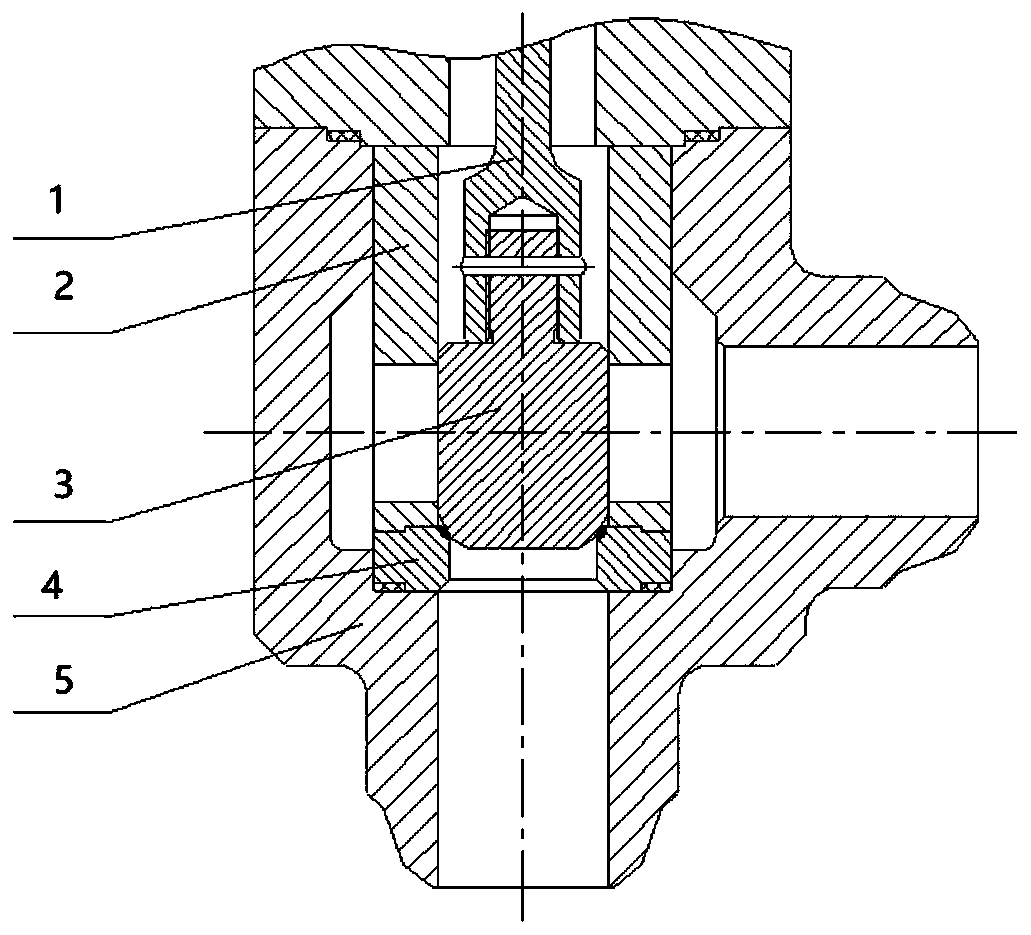
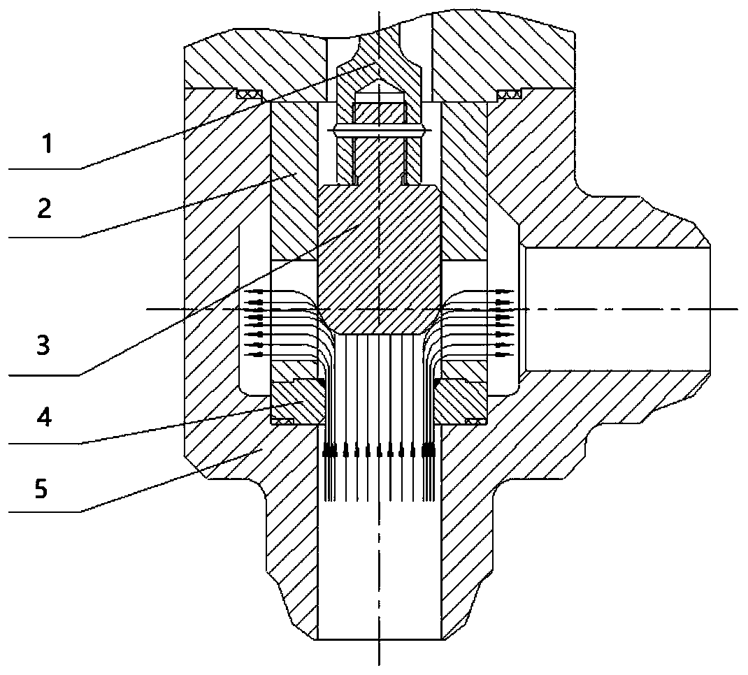
technical field [0001] The invention relates to a split type self-protection sealing surface structure of a regulating valve, relates to a self-protecting sealing surface structure of a regulating valve which reduces erosion and wear, and belongs to the field of processing engineering and valves. Background technique [0002] The existing regulating valve is composed of a valve body, a valve seat, a valve core, a sleeve, a valve stem, etc. ( figure 1 ), the valve core plays a sealing role on the valve seat, and the valve core has no peripheral protection device. During the opening and closing process, the medium directly scours the sealing surface of the valve core ( figure 2 ), and then flow out through the sleeve. After long-term use, the medium will cause serious erosion and wear on the sealing surface of the valve core and valve seat, and the tightness will be reduced. It is necessary to repair the sealing surface of the valve core or replace the new valve core The fre...

Claims


Application Information

Patent Timeline
IPC IPC(8): F16K3/30F16K3/316F16K47/02F16K47/08
CPCF16K3/30F16K3/316F16K47/023F16K47/08
Inventor 张含周蔷姜皓李连翠王周杰刘春玲王恒龚胜泉贾俊阳
Owner SHANGHAI POWER EQUIP RES INST
Learn More