
A plate-shaped rear guide vane of a diagonal flow fan and its design method

The technology of a rear guide vane and a diagonal flow fan is applied to mechanical equipment, components of a pumping device for elastic fluid, pump devices, etc., and can solve the problems of flow field deterioration and insufficient static pressure conversion capacity of guide vanes, etc. Achieve the effect of avoiding flow field deterioration, reducing dynamic and static interference, and improving performance

Active Publication Date: 2020-09-18
HUAZHONG UNIV OF SCI & TECH +1
View PDF10 Cites 0 Cited by
  • Summary
  • Abstract
  • Description
  • Claims
  • Application Information

AI Technical Summary

Problems solved by technology

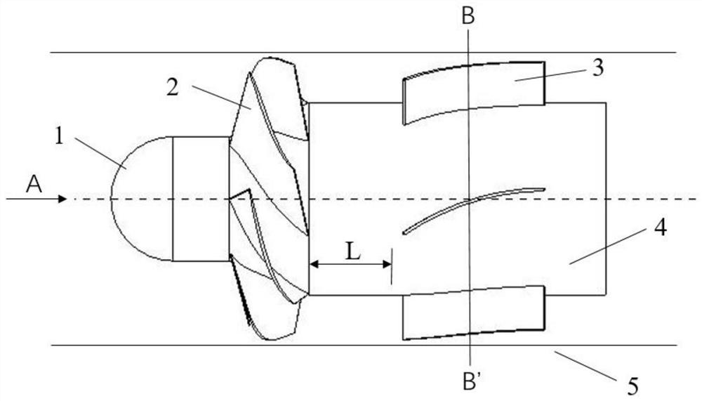
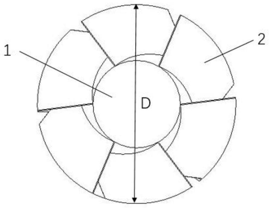
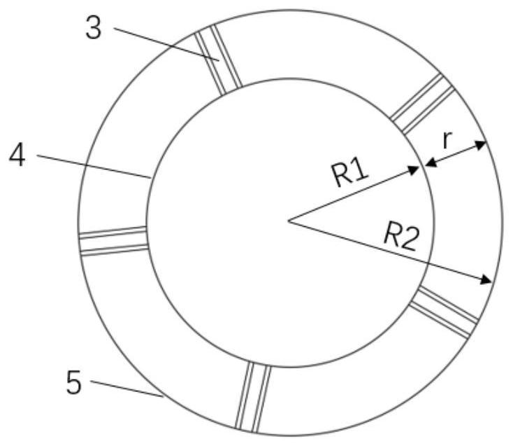
[0007] The invention solves the technical problems of the deterioration of the flow field of the oblique flow fan and the insufficient static pressure conversion capacity of the guide vane in the prior art, and provides a design method of a high-performance plate-shaped rear guide vane, by setting a plate-shaped rear guide vane The number of guide vanes, blade inlet angle, guide vane radius and axial distance between moving and stationary vanes make the oblique flow fan avoid the deterioration of the tail flow field and improve the efficiency of the whole machine

Method used


Image

  • A plate-shaped rear guide vane of a diagonal flow fan and its design method
  • A plate-shaped rear guide vane of a diagonal flow fan and its design method
  • A plate-shaped rear guide vane of a diagonal flow fan and its design method

Examples


Embodiment 1

[0046] Given the diameter of the moving blade impeller D = 492mm, the number of blades N = 6. The number n of plate-shaped rear guide vanes is respectively taken as 5, 6, 7, and 11, and the fans equipped with corresponding plate-shaped rear guide vanes are respectively recorded as N5, Y, N7, and N11. The simulation calculation of four groups of wind turbines is obtained Figure 6 The full pressure curves in the and Figure 7 The total pressure efficiency curve in .

[0047] From Figure 6 and Figure 7 It can be seen that under the condition of small flow rate (Q=5500~6000m 3 / h), the total pressure and total pressure efficiency of the four groups of fans are not much different, and the effect of N7 and Y is better. It can be known that under the condition of small flow, increasing the number of guide vanes can improve the performance of the fan. Under the condition of large flow (Q=6500~7500m 3 / h), it can be seen from the two figures that the comparison relationship b...

Embodiment 2

[0049] Given the diameter of the moving blade impeller D = 492mm, the number of blades N = 6. The radius R of the plate-shaped rear guide vane is respectively taken as 250mm, 300mm, 350mm, and 390mm, and the fans equipped with the corresponding plate-shaped rear guide vane are respectively recorded as R250, R300, R350, and R390.

[0050] The simulation calculation of four groups of wind turbines is obtained Figure 8 The full pressure curves in the and Figure 9 The total pressure efficiency curve in . Over the full flow range, by Figure 8 and Figure 9 It can be seen from the figure that R300 is not dominant when the flow rate is small, but as the flow rate increases, the pressure curve represented by R300 gradually rises and shows a large range of high-performance values. As the flow rate increases, the total pressure of R250 and R300 and The total pressure efficiency curve tends to be consistent. But overall, the R300 solution is better. At this time, the value is 29...

Embodiment 3

[0052] Given the diameter of the moving blade impeller D = 492mm, the number of blades N = 6. Take the axial distance L of moving and stationary blades as 20mm, 40mm, 60mm, 80mm, 100mm, 120mm, and 140mm respectively, and the fans equipped with corresponding plate-shaped rear guide vanes are recorded as L20, L40, L60, L80, L100, L120, and L140 respectively . Carry out simulation calculations on seven groups of fans, and get Figure 10 The total pressure curve and Figure 11 The total pressure curve of the fan at L=80, 100, 120, 140.

[0053] Under the condition of small flow, comprehensive observation Figure 10 and Figure 11 It can be seen that there is little difference between the schemes. Under high flow conditions, from Figure 10 and Figure 11 From the comparison of the two figures, it can be seen that the L80 scheme has the best effect; observing the total pressure, it can be found that when the axial distance is less than 80mm, the performance gradually increas...


PUM


Abstract

The invention discloses a plate-like rear guide blade of an diagonal-flow fan, and a design method of the plate-like rear guide blade and relates to the technical field of fans. The main geometrical parameters of the design of each plate-like rear guide blade include the radius R of the guide blade, the axial distance L of movable and stationary blades, the quantity n of the guide blades and the blade inlet angle alpha of the guide blades; the diameter of impellers of the movable blades of the diagonal-flow fan is recorded as D; the quantity of the impellers of the movable blades of the diagonal-flow fan is recorded as N; the radius R of the guide blades and the diameter D of the impellers of the movable blades of the diagonal-flow fan satisfy the relationship that R / D is larger than or equal to 0.6 and smaller than or equal to 0.7; the axial distance L of the movable and stationary blades and the diameter D of the impellers of the movable blades of the diagonal-flow fan satisfy the relationship that L / D is larger than or equal to 0.16 and smaller than or equal to 0.20; the quantity n of the guide blades and the quantity N of the impellers of the movable blades of the diagonal-flowfan satisfy the relationship that n is larger than or equal to (N-1) and smaller than or equal to (N+1); and the blade inlet angle alpha of the guide blades is equal to the airflow angle of the outlet at 70% to 80% of the blade height position of the diagonal-flow fan. By selecting the design parameters within a limited range of the plate-like rear guide blade disclosed by the invention, deterioration of a flow field can be effectively prevented, and the performance of the diagonal-flow fan can be effectively improved.

Description

technical field [0001] The invention relates to the technical field of fans, and more specifically, to a plate-shaped rear guide vane of a diagonal flow fan and a design method thereof. Background technique [0002] Ventilator is a machine that converts mechanical energy into gas energy. It is widely used in electric power, metallurgy, transportation, fire protection and other fields, and plays an important role in the development of national economy. [0003] The oblique flow fan is named because the airflow is oblique to the axis in the meridian plane of the impeller. It is a fan between axial flow and centrifugal, so it has both the large flow coefficient, high efficiency and centrifugal flow of axial flow. It has the advantages of high pressure coefficient and wide working range. [0004] The rear guide vane oblique flow fan based on axial flow extension design is mainly composed of: impeller, inclined hub, rear guide vane (including guide vane hub) and casing. Axial, ...

Claims


Application Information

Patent Timeline
Patent Type & Authority Patents(China)
IPC IPC(8): F04D25/08F04D29/54
CPCF04D25/08F04D29/544
Inventor 王军吴兰勇栾勇解博超李艺铭李清泉詹婷军
Owner HUAZHONG UNIV OF SCI & TECH
Learn More