A peristaltic pump for low pulse scenarios

A peristaltic pump, low-pulse technology, applied in the field of peristaltic pumps, can solve the problems of shortening the service life of the shaft, reducing the service life of the hose, increasing the compression times of the hose, etc., so as to reduce the energy consumption of operation, improve the service life and wear time Effect

Active Publication Date: 2022-03-18
刘国裕
View PDF6 Cites 0 Cited by
  • Summary
  • Abstract
  • Description
  • Claims
  • Application Information

AI Technical Summary

Problems solved by technology

[0002] see Figure 5 , the pressure roller of the peristaltic pump will stop conveying the liquid at the moment of loosening, so a pulse flow is generated, which limits the use of the peristaltic pump. In order to suppress and reduce the pulsation, the number of pressure rollers is usually increased by one On the one hand, it will reduce the closed liquid volume and reduce the pumping flow rate of the peristaltic pump. On the other hand, since each pressure roller needs a certain pressure between the hose, the more the pressure rollers, the greater the friction of the drive rotation. Large, increasing energy consumption, at the same time, increasing the compression times of the hose, accelerating material fatigue and reducing the service life of the hose
[0003] Further, there are more pressure rollers, the greater the total force between the pressure rollers and the hose, and the hose is usually distributed on one side, and the force on the drive shaft is also biased to one side, which increases the unevenness of the wear of the shaft. shortened shaft life

Method used


Image

  • A peristaltic pump for low pulse scenarios
  • A peristaltic pump for low pulse scenarios
  • A peristaltic pump for low pulse scenarios

Examples


Embodiment Construction

[0019] The following will clearly and completely describe the technical solutions in the embodiments of the present invention with reference to the accompanying drawings in the embodiments of the present invention. Obviously, the described embodiments are only some, not all, embodiments of the present invention. Based on the embodiments of the present invention, all other embodiments obtained by persons of ordinary skill in the art without making creative efforts belong to the protection scope of the present invention.

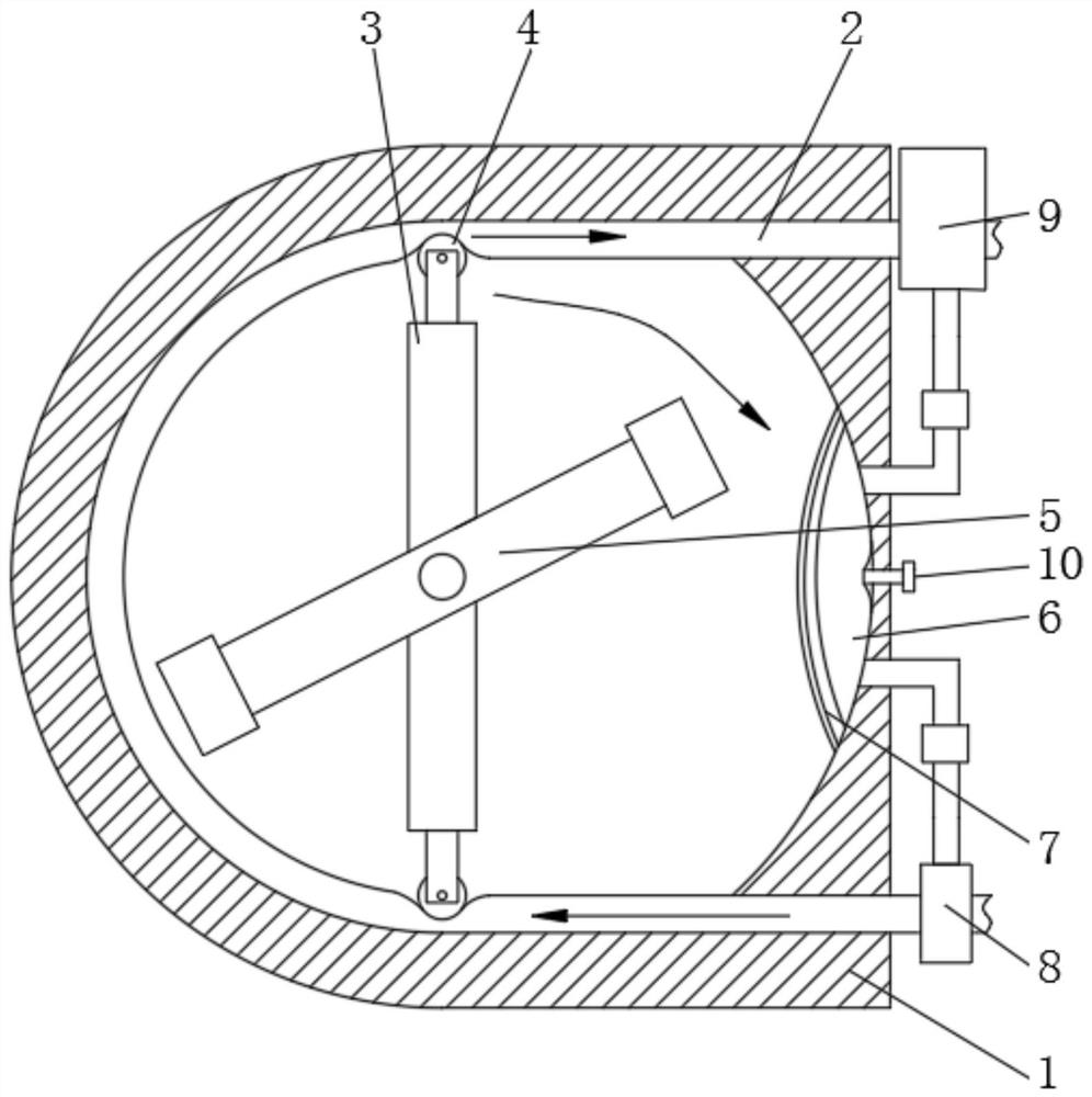
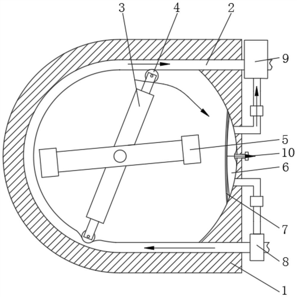
[0020] see Figure 1-4 , a peristaltic pump for low-pulse scenes, including a pump body 1 and a hose 2, the inner wall of the pump body 1 is provided with a hose 2, the middle of the pump body 1 is provided with a driving arm 3 and a compensation arm 5, and the driving arm 3 The pressure roller 4 is fixedly installed at the end of the pump, the driving arm 3 drives the pressure roller 4 to move and squeeze the hose 2, the side of the pump body 1 without the ho...


PUM


Abstract

The invention relates to the technical field of fluid pumps, and discloses a peristaltic pump for low-pulse scenes, including a pump body and a hose, the inner wall of the pump body is provided with a hose, and the middle part of the pump body is provided with a drive arm and a compensating arm, the end of the compensating arm is fixedly equipped with a pressing roller. The peristaltic pump used in the low-pulse scene, when the pressure roller starts to loosen the hose, it drives the compensation arm to compensate the water pressure at the water outlet end of the bladder to compensate, effectively reducing the pulse amplitude, and secondly, it has a large number of pressure rollers Compared with the normal situation, the resistance to the rotation of the driving arm is smaller, which reduces the energy consumption of operation, and the wear time of the hose is also shorter, which improves the service life of the hose, and the force between the pressure roller and the hose is smaller. Small, the force unevenness of the rotating shaft is relatively small. At the same time, due to the additional compensation bag on the side where the hose is not arranged, the force between the compensation arm and the compensation bag is conducive to the uniform force of the rotating shaft, further The service life of the rotating shaft is improved.

Description

technical field [0001] The invention relates to the technical field of fluid pumps, in particular to a peristaltic pump used in low-pulse scenarios. Background technique [0002] see Figure 5 , the pressure roller of the peristaltic pump will stop conveying the liquid at the moment of loosening, so a pulse flow is generated, which limits the use of the peristaltic pump. In order to suppress and reduce the pulsation, the number of pressure rollers is usually increased by one On the one hand, it will reduce the closed liquid volume and reduce the pumping flow rate of the peristaltic pump. On the other hand, since each pressure roller needs a certain pressure between the hose, the more the pressure rollers, the greater the friction of the drive rotation. Large, increasing energy consumption, at the same time, increasing the compression times of the hose, accelerating material fatigue, and reducing the service life of the hose. [0003] Further, there are more pressure rollers...

Claims


Application Information

Patent Timeline
Patent Type & Authority Patents(China)
IPC IPC(8): F04B43/12F04B11/00
CPCF04B43/1253F04B11/00
Inventor 刘国裕
Owner 刘国裕
Why Eureka
Try Eureka