Edge tool box used on mobile nursing vehicle
A mobile nursing and sharp tool box technology, applied in the field of medical supplies, can solve the problems of cutting and separating devices without a syringe needle, an infusion tube, etc., and achieve the effects of low cost, simple operation and simple structure
- Summary
- Abstract
- Description
- Claims
- Application Information
AI Technical Summary
Problems solved by technology
Method used
Image
Examples
Embodiment 1
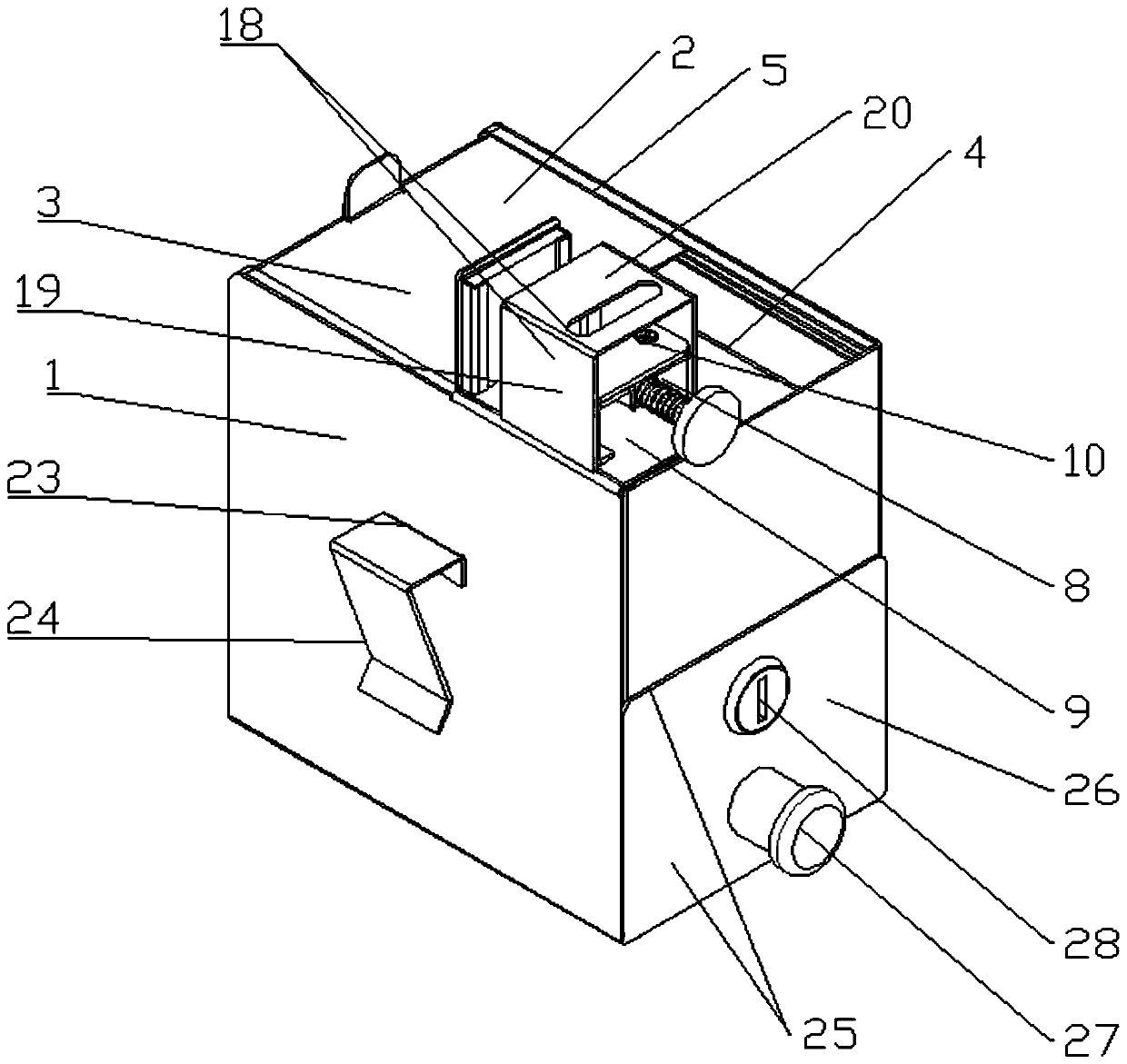
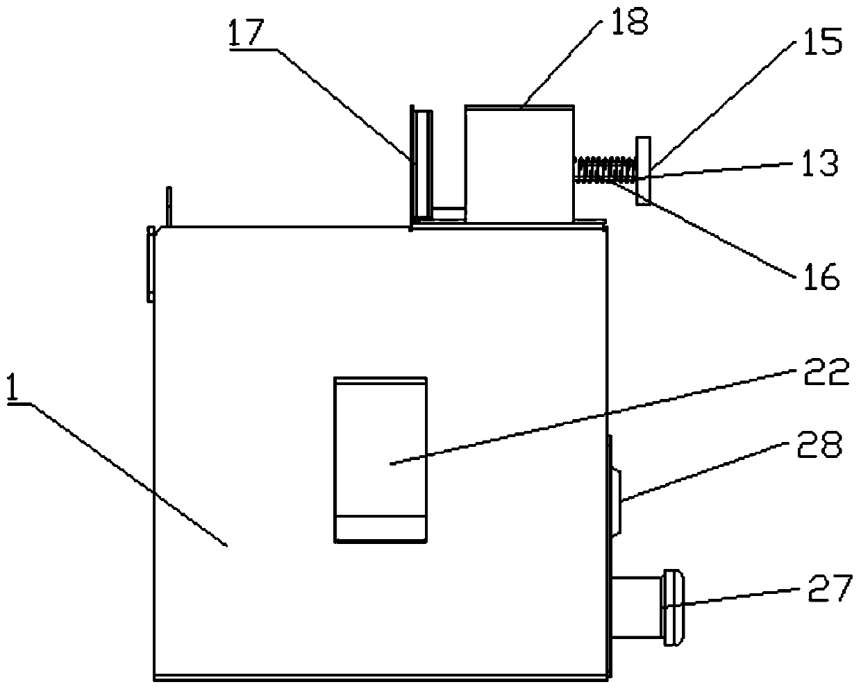
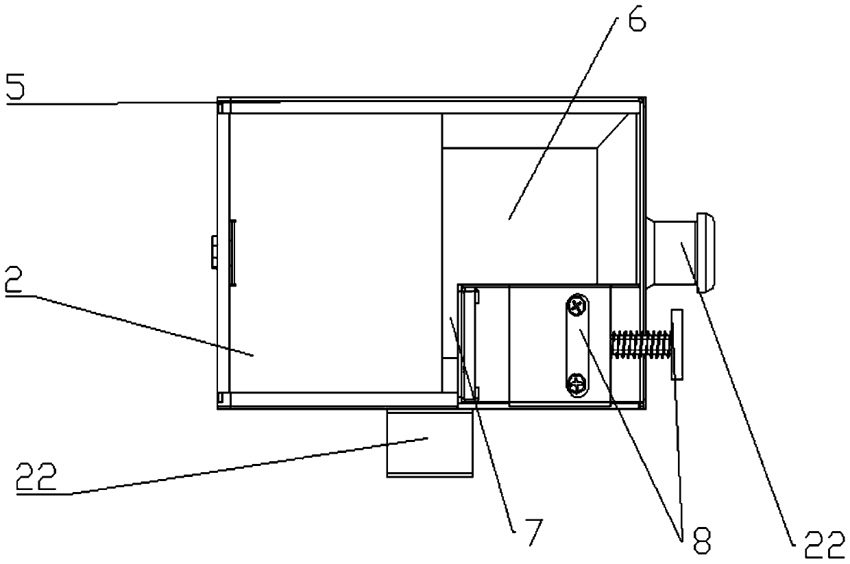
[0044] This embodiment provides a sharps box used on a mobile nursing car, which is provided with a cabinet 1, and a cover sliding area 3 and a cutting area 4 are arranged above the cabinet 1, and the cutting area 4 includes a separation area 6 and a cutting assembly The installation area 7, the separation area 6 and the cutting assembly installation area 7 are arranged along the width direction of the cabinet 1. The cutting assembly installation area 7 includes a cutting assembly 8, and the cutting assembly 8 includes a cutter head base fixedly connected to the side wall of the cabinet 1. Seat 9, the push-type cutter head assembly 10 that is arranged on the cutter head base 9; by being provided with cover plate sliding area 3 and cutting area 4 above the cabinet 1, after the needle tube that is cut is cut off in cutting area 4, in itself Under the gravity of the case, it enters the inside of the box for collection. At the same time, the cover plate 2 that can slide on the top ...
Embodiment 2
[0047] This embodiment is further optimized on the basis of Embodiment 1. Specifically, the push-type cutter head assembly 10 includes a cutter head frame 11 arranged on the cutter head base 9, and a Guide sleeve 12, through the cutter head rod 13 of guide sleeve 12, described cutter head rod 13 comprises the cutter head folder 14 that is arranged on the cutter head rod 13 one ends, is arranged on the press handle 15 of cutter head rod 13 other ends, described A spring 16 is arranged between the pressing handle 15 and the guide sleeve 12, and the spring 16 is covered with the cutter head rod 13; Guide sleeve 12 is set, and cutter head rod 13 is set inside guide sleeve 12, and cutter head rod 13 can carry out relative movement in guide sleeve 12, and the end that cutter head rod 13 is provided with cutter head holder 14 is under the motion of cutter head rod 13 The needle tube assembly placed on the cutter head base 9 is cut off, wherein a spring 16 is arranged between the pres...
Embodiment 3
[0050] This embodiment is further optimized on the basis of Embodiment 1, specifically, a gasket 17 is arranged on the cutter head base 9, and the gasket 17 is arranged on the side close to the cutter head holder 14, so Said gasket 17 is vertically arranged with cutter head base 9, and said gasket 17 is provided with a blade groove 29 near the side of cutter head holder 14; One side of the cutter head holder 14, the spacer 17 is vertically arranged with the cutter head base 9; the blade groove 29 is a groove with a width of 2mm and a depth of 2mm, and the blade on the cutter head holder 14 goes deep into the blade groove 29 during cutting Inside, it is easier and labor-saving for the blade to cut the needle tube by squeezing, and the setting of the spacer 17 is conducive to determining the stroke of the blade 21, and at the same time avoids the accidental injury of the blade 21 to the operator, and improves the safety of use;
[0051] As a preferred technical solution of this ...
PUM
 Abstract
Description
Claims
Application Information
 - R&D
- Intellectual Property
- Life Sciences
- Materials
- Tech Scout
- Unparalleled Data Quality
- Higher Quality Content
- 60% Fewer Hallucinations
Browse by: Latest US Patents, China's latest patents, Technical Efficacy Thesaurus, Application Domain, Technology Topic, Popular Technical Reports.
© 2025 PatSnap. All rights reserved.Legal|Privacy policy|Modern Slavery Act Transparency Statement|Sitemap|About US| Contact US: help@patsnap.com


