A thermal defocus compensation method, storage medium and projection device

A technology of projection equipment and compensation method, which is applied in the direction of using projection device image reproducer, color TV parts, electrical components, etc., which can solve problems such as user interference and achieve the effect of improving satisfaction

Active Publication Date: 2021-09-21
FORMOVIE (CHONGQING) INNOVATIVE TECH CO LTD +1
View PDF14 Cites 0 Cited by
  • Summary
  • Abstract
  • Description
  • Claims
  • Application Information

AI Technical Summary

Problems solved by technology

However, this method is a compensation measure after the user has found that the image is not clear, and the process of focusing will also cause interference to the user

Method used


Image

  • A thermal defocus compensation method, storage medium and projection device
  • A thermal defocus compensation method, storage medium and projection device
  • A thermal defocus compensation method, storage medium and projection device

Examples


Embodiment Construction

[0057] The following will clearly and completely describe the technical solutions in the embodiments of the present invention with reference to the drawings in the embodiments of the present invention. Obviously, the described embodiments are part of the embodiments of the present invention, not all of them. Based on the embodiments of the present invention, all other embodiments obtained by persons of ordinary skill in the art without making creative efforts shall fall within the protection scope of the present invention.

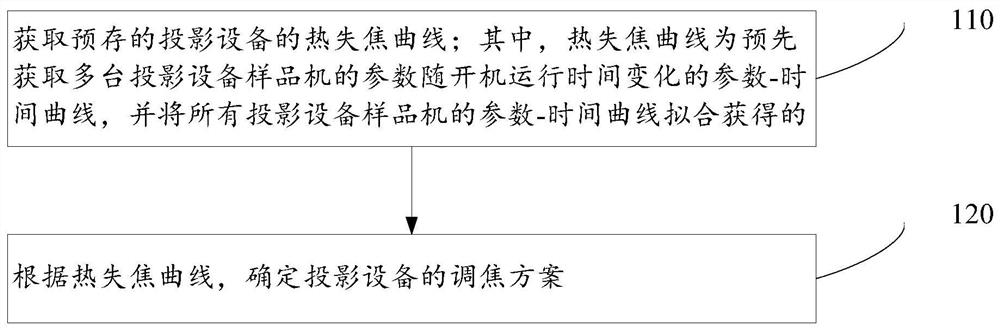
[0058] Such as figure 1 As shown in the schematic step diagram of a thermal defocus compensation method provided by an embodiment of the present invention, the method includes the following steps:

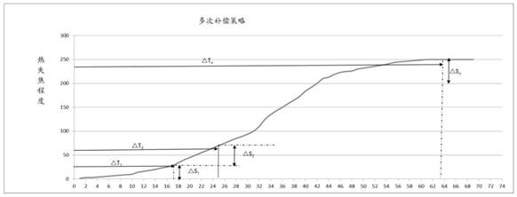
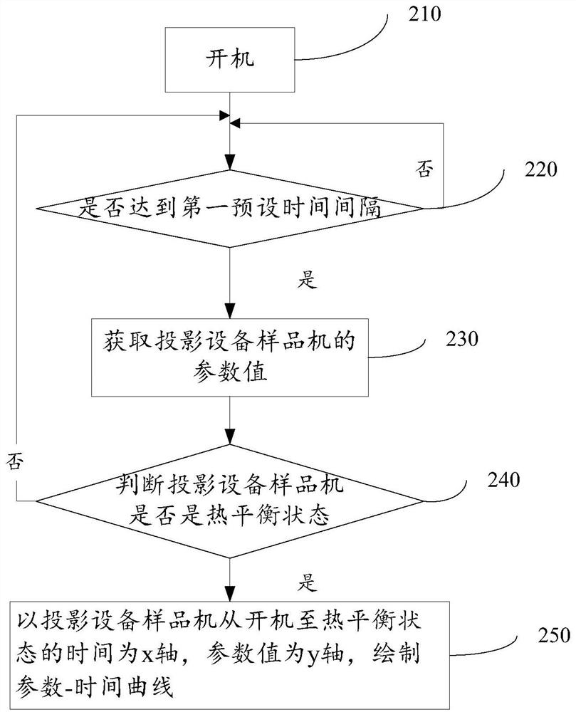
[0059] 110. Obtain the pre-stored thermal defocus curve of the projection device; wherein, the thermal defocus curve is a parameter-time curve obtained in advance that the parameters of multiple projection device samples change with the start-up operation time,...


PUM


Abstract

The present invention relates to a thermal defocus compensation method, which includes obtaining a pre-stored thermal defocus curve of a projection device; wherein, the thermal defocus curve is a parameter obtained in advance that changes with the start-up operation time of the parameters of a plurality of projection device sample machines. The time curve is obtained by fitting the parameter-time curves of all the projection equipment sample machines; according to the thermal defocus curve, the focusing scheme of the projection equipment is determined. The present invention can predict the degree of thermal defocusing of the projection equipment in advance, and determine the focusing scheme of projection in advance according to the degree of thermal defocusing of the projection equipment, so as to prevent the user from seeing unclear pictures and avoid interfering with the normal use of the user. satisfaction. The invention also relates to a storage medium and a projection device.

Description

technical field [0001] The invention relates to the field of projection equipment, in particular to a thermal defocus compensation method, storage medium and projection equipment. Background technique [0002] After the projection device is turned on, there is always a process in which the internal temperature rises until it reaches thermal equilibrium. Therefore, before the thermal balance is reached after starting up, as the internal temperature rises, the size and position of the lens barrel, lens and other parts will change slightly due to the thermal expansion and contraction of the material, resulting in a change in the focal length of the lens, making the original clear picture It becomes blurred due to focal length drift, and the user needs to manually refocus to restore a clear picture. [0003] The prior art has disclosed a projector for thermal defocus compensation. The projector detects the temperature value of the projection lens by setting a temperature sensor...

Claims


Application Information

Patent Timeline
Patent Type & Authority Patents(China)
IPC IPC(8): H04N9/31
CPCH04N9/317
Inventor 谭大治江浩
Owner FORMOVIE (CHONGQING) INNOVATIVE TECH CO LTD
Why Eureka
Try Eureka