
Linear vibrator

A linear vibrator and vibrating part technology, applied in the direction of electrical components, electromechanical devices, etc., can solve the problems of small adjustable space, lower process yield, and large appearance size, so as to reduce the difficulty of process assembly and improve the design of light and thin , The effect of improving the reliability strength

Active Publication Date: 2020-02-11
SHANDONG GETTOP ACOUSTIC
View PDF8 Cites 1 Cited by
  • Summary
  • Abstract
  • Description
  • Claims
  • Application Information

AI Technical Summary

Problems solved by technology

[0002] 1. Compared with the linear vibrators used in electronic products, the existing linear vibrators on the market have higher and stricter requirements on the vibration sense. In order to achieve higher performance, the linear vibrators are often The magnetic induction intensity is high, and the vibration space design is large, resulting in a large product appearance size, which makes it more difficult to assemble with "Z"-shaped shrapnel, reduces the product process yield, and takes up a large installation space of the vehicle-mounted screen;
[0003] 2. Due to the large design size of the linear vibrator, the magnetic gap is too small on one side during the assembly process between the magnetic circuit assembly and the stator assembly, and friction occurs during the vibration process, resulting in noise;
[0004] 3. The elastic element of the through-slot linear vibrator is fixed by welding to the basin frame and the upper and lower shells. The adjustable space of this vibrator structure is small, the requirements for the dimensional accuracy of the material are high, and the cost of a single mold is high. When the product performance needs When changing, high mold repair costs are often incurred

Method used


Image

  • Linear vibrator
  • Linear vibrator
  • Linear vibrator

Examples


Embodiment 1

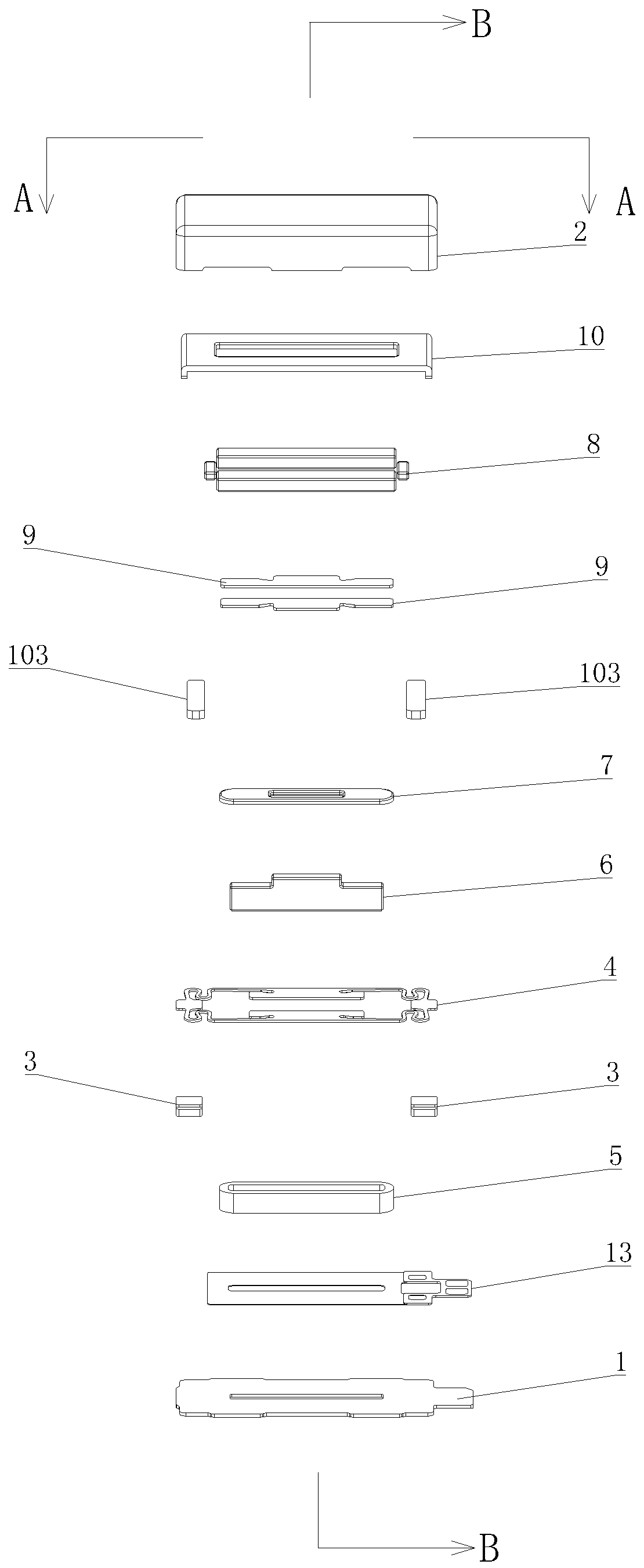
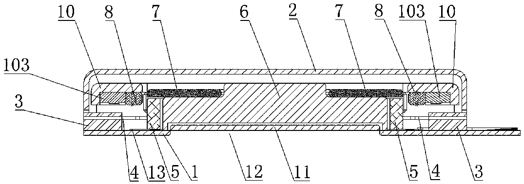
[0053] Embodiment 1: as attached Figure 1-14 As shown, a linear vibrator includes a housing, a magnet and a shrapnel 4, the housing includes an upper housing 2 and a lower housing 1, the upper housing 2 and the lower housing 1 are fixedly connected, and a cavity for accommodating other components is formed inside the housing body, the housing is fixed with two positioning parts, in this embodiment, the positioning part is a support block 3, the two support blocks 3 are respectively welded on the housing, the support block 3 is welded on the lower shell 1, and the two Elastic pieces 4 are fixedly connected between the supporting blocks 3 , and a through hole 41 for accommodating the coil 5 is provided in the middle of the elastic pieces 4 .

[0054] like Figure 1-4 As shown, the elastic sheet 4 is a flat elastic sheet, and the flat elastic sheet usually refers to a spring sheet that undergoes vertical elastic deformation in a plane, which is hollowed out on a flat elastic ma...

Embodiment 2

[0066] Embodiment 2: as attached Figure 15 And attached Figure 16 As shown, the vibrating part further includes two second vibrating parts 46 disposed opposite to each other, the second vibrating parts 46 are connected to the vibrating arm 44, and the second vibrating parts 46 are in the shape of a rectangular plate.

[0067] Other structures are the same as in Embodiment 1.

Embodiment 3

[0068] Embodiment 3: as attached Figure 17 As shown, the vibrating part further includes two second vibrating parts 46 disposed opposite to each other. The second vibrating part 46 is connected with the first vibrating part 43 to form an integrated structure. The second vibrating part 46 is in the shape of a rectangular plate.

[0069] Other structures are the same as in Embodiment 1.


PUM


Abstract

The invention provides a linear vibrator. The linear vibrator comprises a shell, a magnet and an elastic sheet. The elastic sheet is a flat elastic sheet. The elastic sheet comprises a fixed portion,a vibration portion and a vibration arm. A bending portion is formed near an end portion, connected with the fixed portion, of the vibration arm, and a rib width of the vibration arm is smaller than the rib width of the vibration portion and is smaller than a width of the fixed portion. The elastic sheet is fixed between two supporting blocks so that a vibration space is saved, assembling difficulty of a manufacturing process is greatly reduced, a light and thin design of a product is favorably realized, and a manufacturing yield is improved. A plurality of magnets are arranged and are placedat a periphery of a coil. An upper end and a lower end of each magnet are fixed between a basin stand and a non-magnetic-conductive pole piece and are connected with the elastic piece in a welding mode so as to greatly improve a utilization rate of a magnetic circuit, shorten response time of a product, improve a vibration sense, improve overall reliability strength of the magnetic circuit, and solve a problem that the magnetic circuit falls off in an environment reliability test.

Description

technical field [0001] The invention relates to the field of linear vibrating equipment, in particular to a linear vibrator. Background technique [0002] 1. Compared with the linear vibrators used in electronic products, the existing linear vibrators on the market have higher and stricter requirements on the vibration sense. In order to achieve higher performance, the linear vibrators are often The magnetic induction intensity is high, and the vibration space design is large, resulting in a large product appearance size, which is more difficult to assemble with "Z"-shaped shrapnel, lowers the product process yield, and occupies a large installation space of the vehicle-mounted screen; [0003] 2. Due to the large design size of the linear vibrator, the magnetic gap is too small on one side during the assembly process between the magnetic circuit component and the stator component, and friction occurs during the vibration process, resulting in noise; [0004] 3. The elastic...

Claims


Application Information

Patent Timeline
Patent Type & Authority Applications(China)
IPC IPC(8): H02K33/02
CPCH02K33/02
Inventor 王海童邱士嘉
Owner SHANDONG GETTOP ACOUSTIC
Learn More