Box filling machine for refractory material recycling
A refractory material and cartoning machine technology, applied in the directions of transportation and packaging, loading/unloading, grain processing, etc., can solve the problems of inconvenient collection and packing of refractory particles, achieve high work efficiency, avoid blocking, and simple operation convenient effect
- Summary
- Abstract
- Description
- Claims
- Application Information
AI Technical Summary
Problems solved by technology
Method used
Image
Examples
Embodiment 1
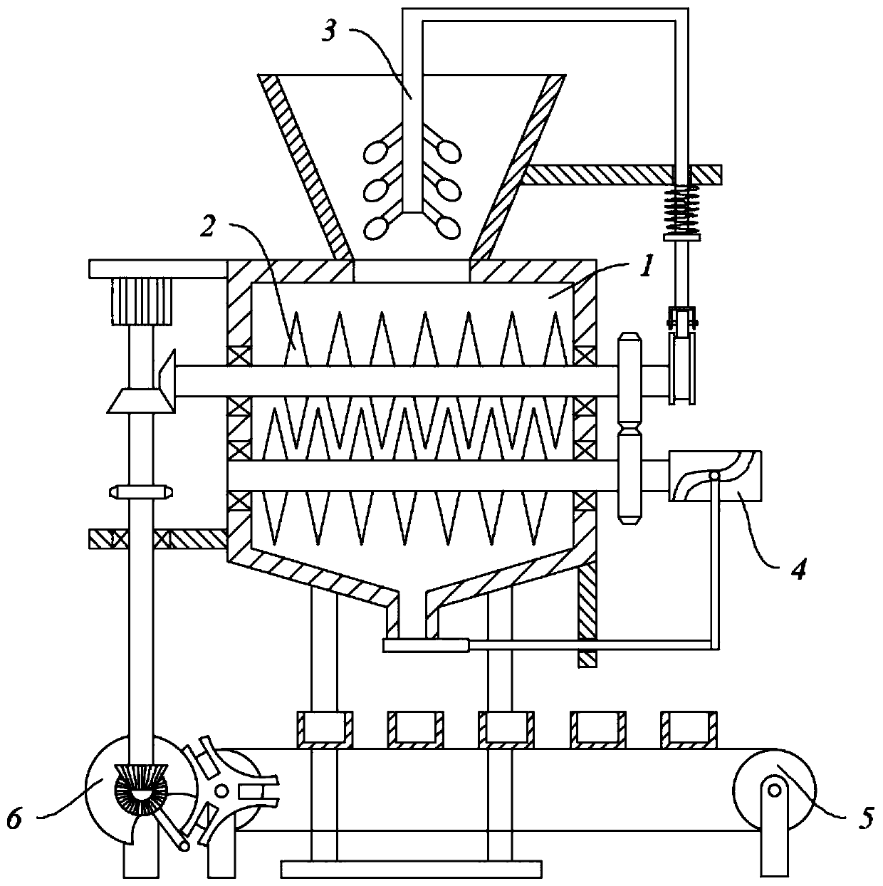
[0045] refer to figure 1 , a cartoning machine for recycling refractory materials, comprising a housing 1, a crushing component 2, a boxing component 5, a discharge component 4 and a transmission component 6;
[0046] The housing 1 includes a base 101, legs 102, a crushing chamber 103, a discharge pipe 104, and a lower hopper 105. The bottom of the crushing chamber 103 is connected with a discharge pipe 104, and the top is connected with a lower hopper 105; the bottom of the crushing chamber 103 is symmetrical A leg 102 is connected, and the base 101 is fixedly connected to the bottom of the leg 102; the crushing chamber 103 is provided with a crushing assembly 2; the discharge pipe 104 is provided with a discharge assembly 4; the box assembly 5 is provided in the discharge pipe 104 Below: the crushing assembly 2 cooperates with the box loading assembly 5 through the transmission assembly 6 .
Embodiment 2
[0048] refer to figure 1 , a cartoning machine for recycling refractory materials, comprising a housing 1, a crushing component 2, a boxing component 5, a discharge component 4 and a transmission component 6;
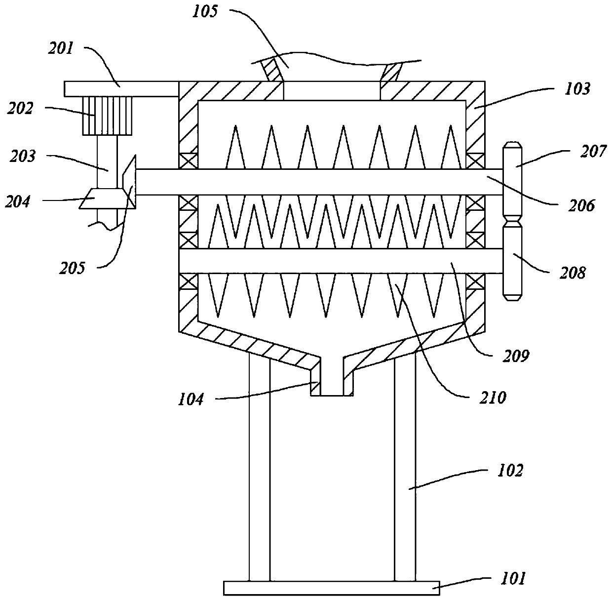
[0049] The housing 1 includes a base 101, legs 102, a crushing chamber 103, a discharge pipe 104, and a lower hopper 105. The bottom of the crushing chamber 103 is connected with a discharge pipe 104, and the top is connected with a lower hopper 105; the bottom of the crushing chamber 103 is symmetrical A leg 102 is connected, and the base 101 is fixedly connected to the bottom of the leg 102; the crushing chamber 103 is provided with a crushing assembly 2; the discharge pipe 104 is provided with a discharge assembly 4; the box assembly 5 is provided in the discharge pipe 104 Below: the crushing assembly 2 cooperates with the box loading assembly 5 through the transmission assembly 6 .
[0050] refer to figure 2 , wherein, the crushing assembly 2 includes a mounting pl...
Embodiment 3
[0064] Wherein, the same or corresponding components as in Embodiment 1 and Embodiment 2 adopt the reference numerals corresponding to Embodiment 1 and Embodiment 2. For the sake of brevity, only the differences from Embodiment 2 are described below. The difference between this embodiment and embodiment two is:
[0065] The bottom of the crushing chamber 103 is a structure with a large top and a small bottom, and the discharge pipe 104 is connected to the lowest center of the bottom of the crushing chamber 103 to guide the crushed materials by itself;
[0066] The outer diameter of the outlet of the discharge pipe 104 is smaller than the outer diameter of the top opening of the material receiving box 504, which is convenient for material receiving.
PUM
 Abstract
Description
Claims
Application Information
 - R&D Engineer
- R&D Manager
- IP Professional
- Industry Leading Data Capabilities
- Powerful AI technology
- Patent DNA Extraction
Browse by: Latest US Patents, China's latest patents, Technical Efficacy Thesaurus, Application Domain, Technology Topic, Popular Technical Reports.
© 2024 PatSnap. All rights reserved.Legal|Privacy policy|Modern Slavery Act Transparency Statement|Sitemap|About US| Contact US: help@patsnap.com


