
Bionic compound eye image acquisition device

An image acquisition device, bionic compound eye technology, applied in image communication, TV, color TV components, etc., can solve the problem of low spatial resolution of the compound eye, achieve simple and convenient steps, increase the imaging field of view, and achieve good imaging effect of effect

Inactive Publication Date: 2020-02-07
TIANJIN UNIV
View PDF7 Cites 0 Cited by
  • Summary
  • Abstract
  • Description
  • Claims
  • Application Information

AI Technical Summary

Problems solved by technology

[0005] The purpose of the present invention is to overcome the deficiencies in the prior art, to provide a curved surface structure bionic compound eye image acquisition device based on the principle of overlapping compound eyes, to overcome the low spatial resolution of the compound eye caused by the small size of the small eye in the traditional compound eye model problems while making full use of the image sensor space and reducing system cost

Method used


Image

  • Bionic compound eye image acquisition device
  • Bionic compound eye image acquisition device
  • Bionic compound eye image acquisition device

Examples


Embodiment Construction

[0026] In order to further understand the invention content, characteristics and effects of the present invention, the following examples are given, and detailed descriptions are as follows in conjunction with the accompanying drawings:

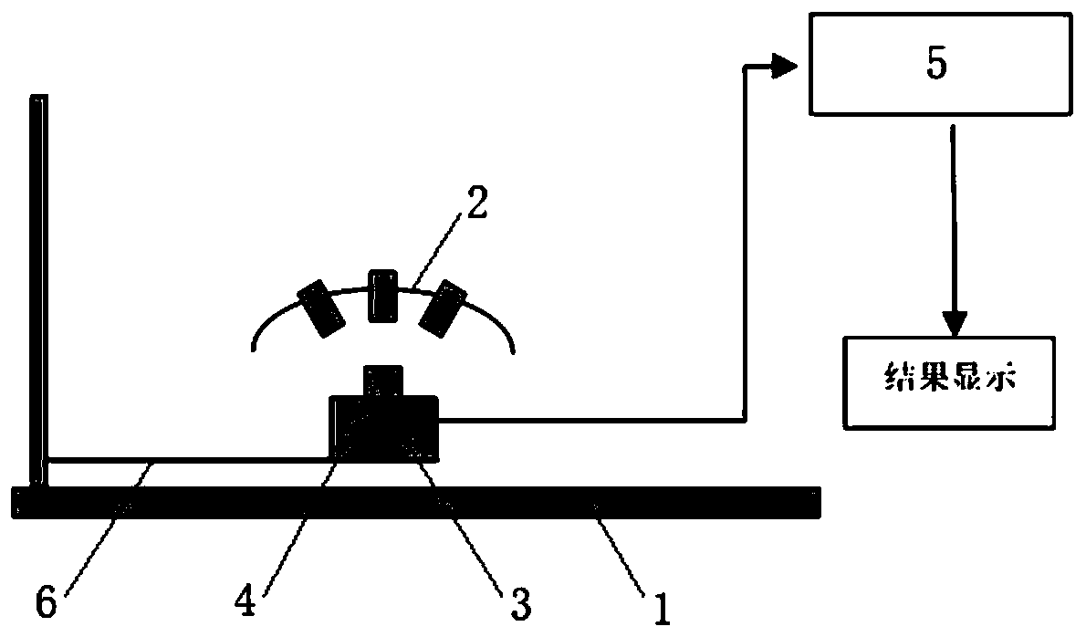
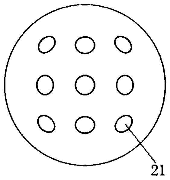
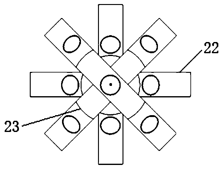
[0027] The invention relates to the manufacture of bionic compound eye devices, structure optimization and collection of compound eye image information. as attached Figure 1 to Figure 3 As shown, a bionic compound eye image acquisition device includes a visual experiment platform 1 , an ommatidium system 2 , an image sensor 3 , a zoom lens 4 and a data processing system 5 .

[0028] The ommatidium system 2 includes several ommatidium lenses 21 arranged in a matrix and distributed on a spherical surface with a set curvature radius, and the curvature radius of the spherical surface is 10cm-15cm. The convex spherical surface of the ommatidium system 2 faces the picture to be imaged. In this embodiment, the ommatidium system 2 adopts nine omma...


PUM

PropertyMeasurementUnit
Radius of curvatureaaaaaaaaaa
Focal lengthaaaaaaaaaa

Abstract

The invention discloses a bionic compound eye image acquisition device. The bionic compound eye image acquisition device comprises a visual experiment table, a small eye system, an image sensor, a zoom lens and a data processing system; the small eye system comprises a plurality of small spectacle lenses, the plurality of small spectacle lenses are arranged in a matrix and distributed on a spherical surface with a set curvature radius, and a convex spherical surface of the small eye system faces a picture to be imaged; the image sensor is fixed on the visual experiment table and is positionedon the concave spherical surface side of the ommatidium system; the zoom lens is connected with the image sensor, and the center of the zoom lens is opposite to a small spectacle lens located in the center of the small eye system; and the image sensor is connected with the data processing system. According to the method, the problem that the compound eye spatial resolution is too low due to the small eye size in a traditional compound eye model is solved, meanwhile, the space of the image sensor can be fully utilized, and the system cost is reduced.

Description

technical field [0001] The invention relates to compound eye imaging technology, in particular to a bionic compound eye image acquisition device. Background technique [0002] Compound eye imaging technology is an innovative and interdisciplinary emerging research direction integrating biology, optoelectronics, informatics and other disciplines. The insect compound eye vision system has the characteristics of large field of view and high detection sensitivity of moving targets, so it has advantages that other imaging methods cannot match in some military and civilian applications. [0003] In recent years, precision instruments have developed towards low energy consumption, small size, and high intelligence. Today's electronic devices and mechanical devices have been microfabricated. However, the bottleneck in realizing the miniaturization of systems such as smart weapon identification and micro air vehicle identification lies in the design of micro-optical systems. The t...

Claims


Application Information

Patent Timeline
IPC IPC(8): H04N5/225
CPCH04N23/50H04N23/55
Inventor 宋乐李祥正刘涛
Owner TIANJIN UNIV
Learn More