
A method for analyzing the transmission path of vehicle body vibration

A technology of path analysis and vibration transmission, applied in the field of automobile manufacturing, can solve problems such as difficulty, complicated implementation process, low efficiency, etc., and achieve the effect of improving efficiency

Active Publication Date: 2021-06-18
SAIC-GM-WULING AUTOMOBILE CO LTD
View PDF0 Cites 0 Cited by
  • Summary
  • Abstract
  • Description
  • Claims
  • Application Information

AI Technical Summary

Problems solved by technology

This method can identify the uncoupled frequency response function through the coupling frequency response function and avoid splitting the system, but it needs to apply artificial excitation during the operation of the working condition, which makes the implementation process complicated and difficult, and the efficiency is low

Method used


Image

  • A method for analyzing the transmission path of vehicle body vibration
  • A method for analyzing the transmission path of vehicle body vibration
  • A method for analyzing the transmission path of vehicle body vibration

Examples


Embodiment Construction

[0016] The present invention will be described in further detail below in conjunction with the accompanying drawings.

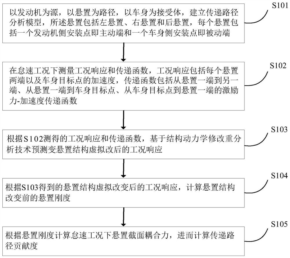
[0017] A flow chart of a vehicle body vibration transmission path in an embodiment of the present invention is as follows figure 1 As shown, the method includes:

[0018] S101. Establish a transfer path analysis model with the engine as the source, the mount as the path, and the body as the receiver. The mount includes a left mount, a right mount, and a rear mount, and each mount includes an engine side The mounting point is the active end and one body side mounting point is the passive end;

[0019] This step is used to establish the "source-path-recipient" model, that is, the transfer path analysis model. In this embodiment, the engine is used as the source, the mount is used as the path, and the vehicle body is used as the receiver to establish a transfer path analysis model. The suspension in this embodiment includes left suspension, right suspension a...


PUM


Abstract

The invention discloses a vehicle body vibration transmission path analysis method. The method includes: establishing a transfer path analysis model; measuring the operating condition response and transfer function under the idle speed condition; according to the measured operating condition response and transfer function, modifying the reanalysis technology based on structural dynamics to predict the suspension structure after the virtual change According to the working condition response after the virtual change of the mount structure, the mount stiffness before the mount structure change is calculated; the coupling force of the mount section under the idle speed condition is calculated according to the mount stiffness, and then the transmission path contribution is calculated Spend. The present invention predicts the system response after the virtual modification of the local structure based on the structural dynamics modified reanalysis technology, avoids the direct experimental measurement of the frequency response function of the vehicle body and the dynamic stiffness of the suspension, improves the efficiency of the transmission path analysis, and provides a comprehensive solution for the vibration transmission of the vehicle body. Path analysis lays the groundwork.

Description

technical field [0001] The invention belongs to the technical field of automobile manufacturing, and in particular relates to a vibration transmission path analysis method of a vehicle body based on structural dynamics reanalysis technology. Background technique [0002] Since the "source-path-receptor" model was proposed, transfer path analysis (TPA) has been greatly developed as a method to analyze and deal with vehicle vibration and noise problems. Traditional TPA, as the first proposed TPA, has the advantages of high precision and mature method, but it is time-consuming and labor-intensive due to the need to decouple active components. Although the subsequent development of TPA can shorten the experimental time, it needs to sacrifice the accuracy, and the TPA based on the inverse substructure method is difficult to improve the vibration transmission path analysis process of the vehicle body. [0003] Based on the traditional transfer path analysis method proposed by Ger...

Claims


Application Information

Patent Timeline
Patent Type & Authority Patents(China)
IPC IPC(8): G01M7/02G01M17/007
CPCG01M7/02G01M17/007
Inventor 王昆王玉雷李雪平罗德洋倪晓波朱平王增伟
Owner SAIC-GM-WULING AUTOMOBILE CO LTD
Learn More