Variable section device for automatic start-stop of turbine fan

An automatic start-stop, turbo fan technology, applied in the direction of adjusting air supply, combustion method, combustion chamber, etc., can solve the problems of low flow rate and high energy consumption at the bottom of the absorption tower, and achieve the effect of saving operating costs, promoting operation and reducing burden

Pending Publication Date: 2020-02-04
商逸帆
View PDF0 Cites 0 Cited by
  • Summary
  • Abstract
  • Description
  • Claims
  • Application Information

AI Technical Summary

Problems solved by technology

[0002] In the actual operation of the boiler or sintering machine, its load will change according to external conditions (for example, it will operate at low load during economic depression, and it will operate at full load during economic prosperity). When operating at full load, the flow velocity at the bottom of the dry desulfurization absorption tower can Meet the requirement of no ash falling, no need to make up flue gas, but in low-load operation, the flow velocity at the bottom of the absorption tower is low, and the circulating flue needs to make up the flue gas back to the bottom of the absorption tower to ensure that the flow rate at the bottom of the tower is high and no ash falls. The flue gas in the supplementary circulation flue consumes more energy. From the owner’s point of view, their devices are under low load, while the subsequent desulfurization device basically requires more than 75% of the load to operate, and the energy consumption is relatively high.

Method used


Image

  • Variable section device for automatic start-stop of turbine fan
  • Variable section device for automatic start-stop of turbine fan
  • Variable section device for automatic start-stop of turbine fan

Examples


Embodiment Construction

[0041] The following will clearly and completely describe the technical solutions in the embodiments of the present invention with reference to the accompanying drawings in the embodiments of the present invention. Obviously, the described embodiments are only some, not all, embodiments of the present invention. Based on the embodiments of the present invention, all other embodiments obtained by persons of ordinary skill in the art without making creative efforts belong to the protection scope of the present invention.

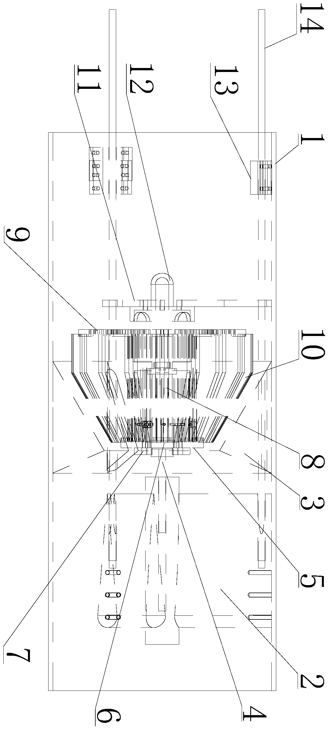
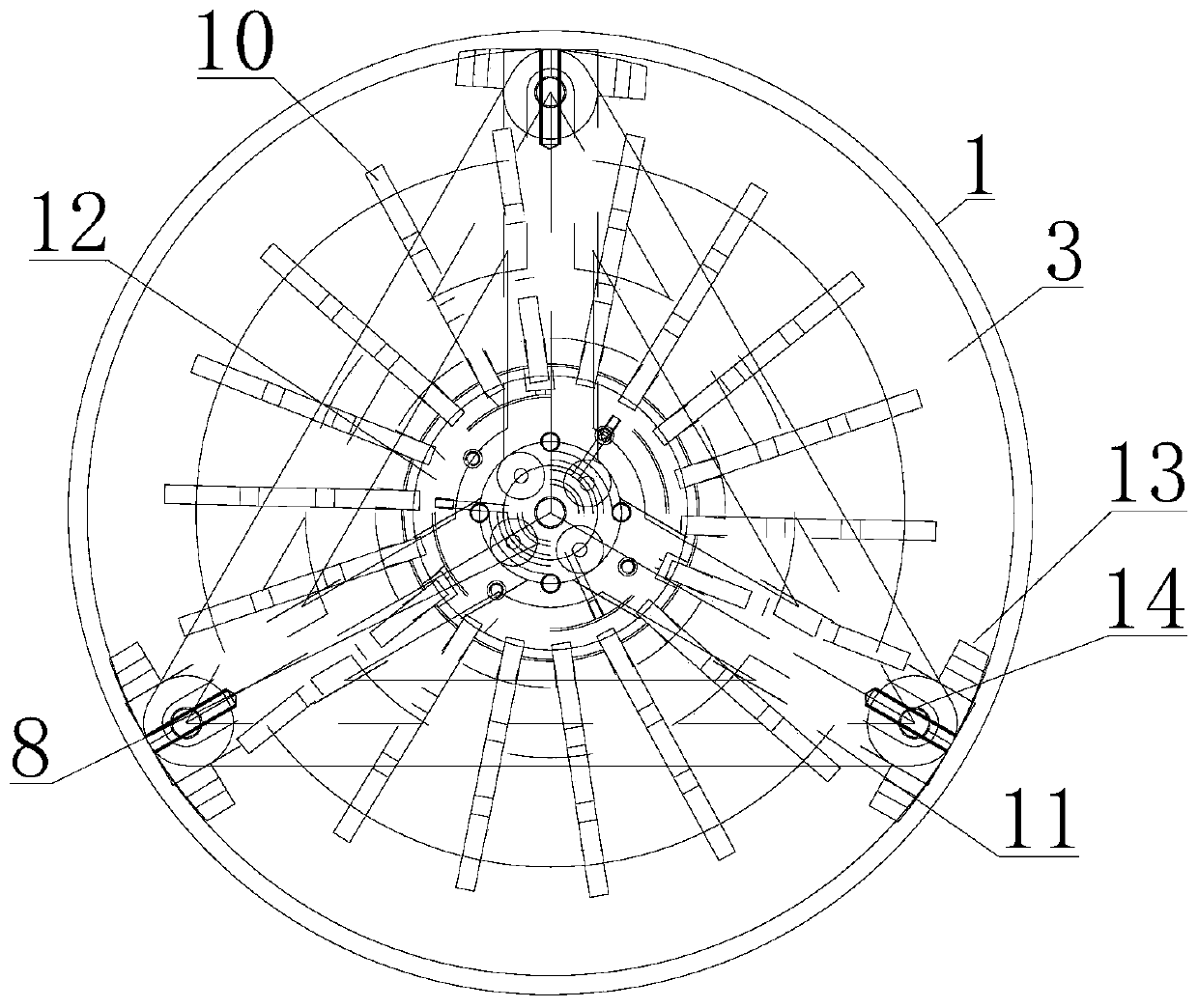
[0042] see Figure 1-12 , a turbofan automatic start and stop variable cross-section device, including a flue 1, a lower rail bracket 2, a variable cross-section flue 3, a central shaft 4, a bearing seat 5, a main bearing 6, a lower dust cover 7, a motor 8, The impeller 9, the blade 10, the upper sliding frame 11, the upper dust cover 12, the upper sliding rail bracket 13 and the sliding rail 14, the inner bottom of the flue 1 is provided with the lower rail b...


PUM


Abstract

The invention discloses a variable section device for automatic start-stop of a turbine fan. The variable section device comprises a flue, a lower sliding rail bracket, a variable section flue, a lower dust-proof cover, a motor, an impeller, blades, an upper sliding frame, an upper dust-proof cover, an upper sliding rail bracket and a sliding rail. The turbine fan rotates to change the flowing direction of flue gas in the flue and increase the flowing speed, then up-down displacement of the turbine fan in the vertical direction is utilized to control the rotating power of the turbine fan, therotating speed of the turbine fan can be changed in real time, up-down moving of the turbine fan is conducted through thrust of the flue gas, the bevel part in the variable section flue can be matchedwith the inclined angle of the blades of the turbine fan, thus the turbine fan can move up and down in the vertical direction, the bevel is divided into an upper cone part and a lower cone part, impact of the flue gas in the original flue to the device can be effectively reduced, flue gas energy loss is reduced, the device can automatically operate, the rotating speed of the turbine fan does notneed to be adjusted in a manual mode, the burden of workers is effectively relieved, and the cost is lowered.

Description

technical field [0001] The invention relates to the technical field of flue gas acceleration, in particular to a turbofan automatic start-stop variable section device. Background technique [0002] In the actual operation of the boiler or sintering machine, its load will change according to the external conditions (for example, it will operate at low load during economic depression, and it will operate at full load during economic prosperity). When operating at full load, the flow velocity at the bottom of the dry desulfurization absorption tower can Meet the requirement of no ash fall, no need to make up the flue gas, and when the load is low, the flow velocity at the bottom of the absorption tower is low, the circulating flue needs to make up the flue gas back to the bottom of the absorption tower to ensure that the flow rate at the bottom of the tower is high and no ash fall occurs, but The flue gas of the supplementary circulation flue consumes more energy. From the owne...

Claims


Application Information

Patent Timeline
IPC IPC(8): F23M9/00F23N3/00
CPCF23M9/003F23N3/005
Inventor 商逸帆冯薇蔡子城尹阳鑫蒋烨鹏郭佳豪马乐乐
Owner 商逸帆
Why Eureka
Try Eureka