
Embedded rudder surface control mechanism of unmanned aerial vehicle

A control mechanism and rudder surface technology, applied in the directions of non-power amplification, aircraft transmission, aircraft power transmission, etc., can solve the problems of small space inside the wing and difficult to achieve, and achieve convenient installation, easy engagement, and simple structure. Effect

Active Publication Date: 2020-02-04
XIAN AISHENG TECH GRP +1
View PDF7 Cites 1 Cited by
  • Summary
  • Abstract
  • Description
  • Claims
  • Application Information

AI Technical Summary

Problems solved by technology

However, the rudder surface of the UAV is generally located at the trailing edge of the wing surface, and the internal space of the wing is small. The general rudder surface control mechanism must ensure that there are no exposed parts and not destroy the original aerodynamic shape of the UAV, which is difficult to achieve.

Method used


Image

  • Embedded rudder surface control mechanism of unmanned aerial vehicle
  • Embedded rudder surface control mechanism of unmanned aerial vehicle
  • Embedded rudder surface control mechanism of unmanned aerial vehicle

Examples


Embodiment Construction

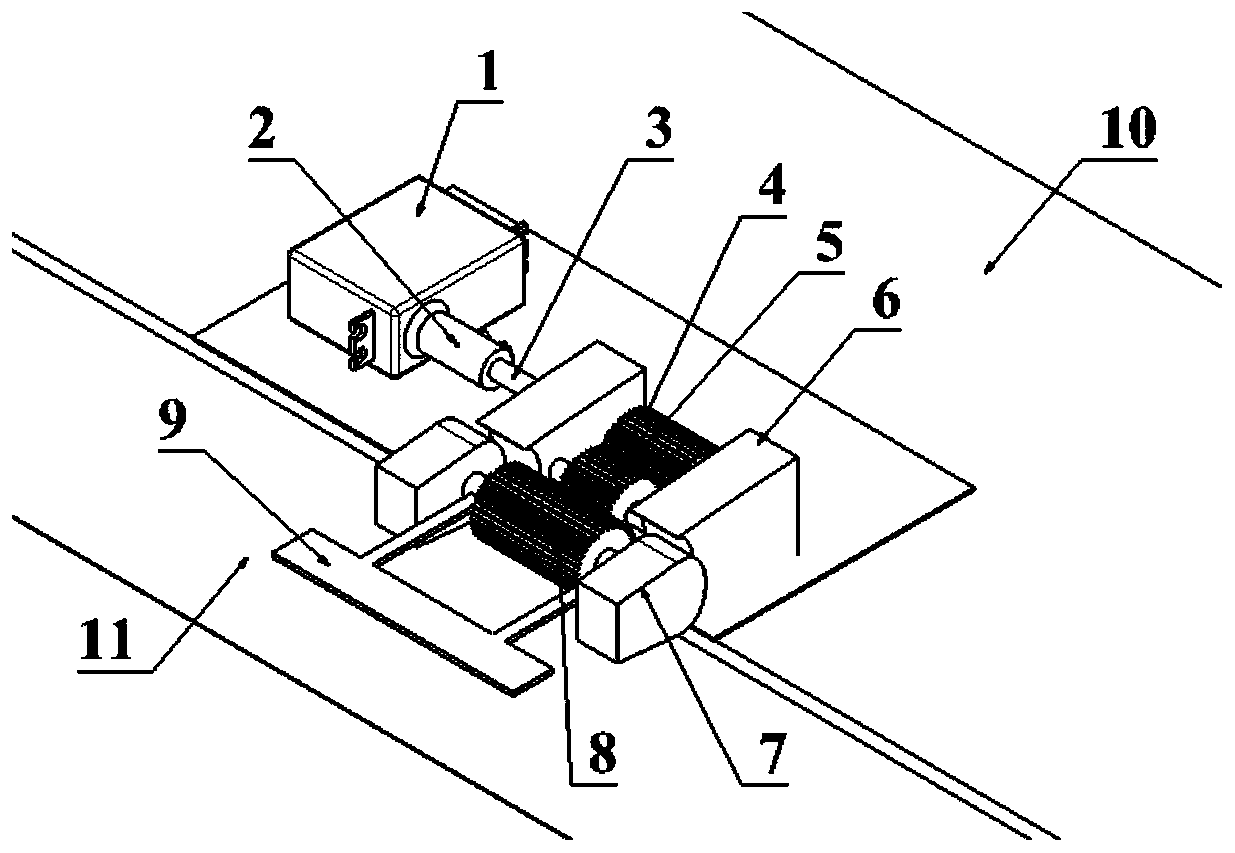
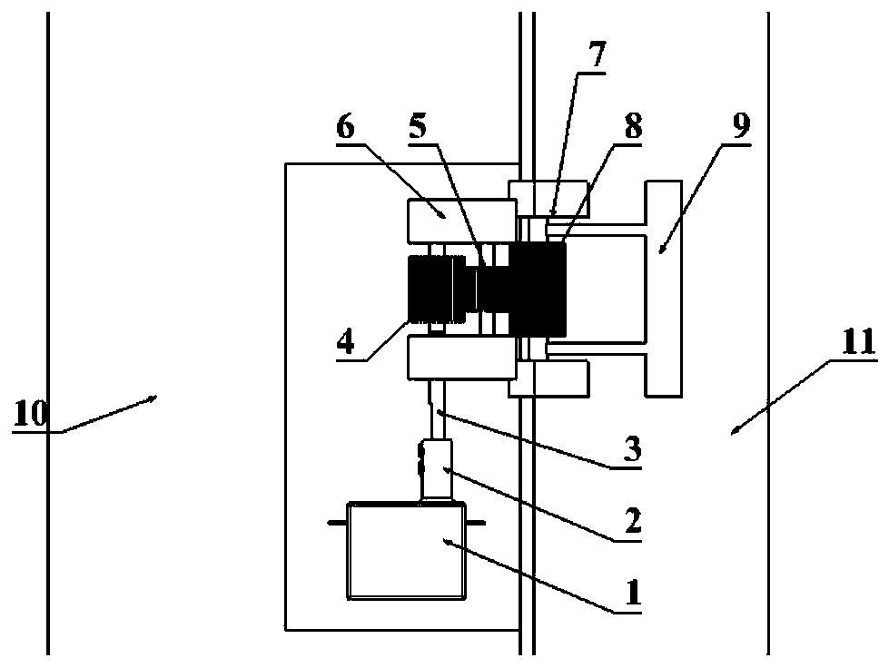
[0024] An embodiment of the present invention is a built-in unmanned aerial vehicle control surface control mechanism.

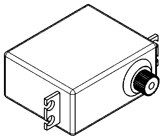
[0025] refer to Figure 1 to Figure 5 In this embodiment, the embedded UAV rudder surface control mechanism consists of a steering gear 1, a connecting sleeve 2, a driving gear shaft 3, a driving gear 4, a driving gear 5, a driving gear mounting seat 6, a driven gear bracket 7, The driven gear 8, the moving plate 9, the wing 10, the rudder surface 11, the end screw 12, the first screw 13 and the second screw 14, wherein the steering gear 1 and the driving gear mount 6 are respectively fixed on the wing 10, the steering gear is located on the side of the end of the driving gear mounting seat 6, the driving gear 4 and the transmission gear 5 are respectively installed in the middle of the driving gear mounting seat 6, the driving gear 4 and the transmission gear 5 are meshed for transmission, and the driving gear shaft 3 protrudes The end of the driving gear ...


PUM


Abstract

The invention discloses an embedded rudder surface control mechanism of an unmanned aerial vehicle. The embedded rudder surface control mechanism consists of a steering engine, a driving gear, a transmission gear and a driven gear. The steering engine and a driving gear mounting seat are fixed in a wing, the steering engine is arranged on one side of the driving gear mounting seat, and the drivinggear and the transmission gear are arranged in the middle of the driving gear mounting seat. The two ends of a connecting sleeve are connected with the steering engine and a rotating shaft of the driving gear correspondingly. The driven gear and an actuating piece are installed in the steering engine through a driven gear bracket, the actuating piece is fixedly connected with a rotating shaft ofthe driven gear, the rotating shaft of the driven gear coincides with a rotating shaft of a rudder surface, and the transmission gear and the driven gear are meshed at a gap between the rear edge of the wing and the front edge of the rudder surface. The steering engine drives the driving gear to rotate and drives the driven gear to rotate through the transmission gear, and the driven gear drives the actuating piece to rotate to extrude the rudder surface, and therefore the rudder surface is driven to rotate. The rudder surface control mechanism is simple in structure and convenient to install;and the transmission ratio of the steering engine and the rudder surface can be adjusted by changing the number of teeth of each gear, so that the control precision is adjusted.

Description

[0001] Field [0002] The invention relates to the field of unmanned aerial vehicles and automatic control, in particular to a built-in unmanned aerial vehicle rudder surface control mechanism. Background technique [0003] At present, UAVs have been widely used in both civilian and military fields. Among them, fixed-wing UAVs have been widely used. The rudder surface of a fixed-wing UAV generally includes flaps and ailerons on the wings, elevators on the horizontal tail and rudders on the vertical tail, which are used to control the aircraft. [0004] The rudder surface control mechanism of fixed-wing drones generally uses exposed rocker arms and connecting rods to connect the steering gear and rudder surface for rudder surface control. This rudder surface control mechanism increases the exposed area of ​​the body. Although it can rectify the exposed part, it still destroys the original aerodynamic shape of the drone and reduces the lift-to-drag ratio of the drone. If one ...

Claims


Application Information

Patent Timeline
Patent Type & Authority Applications(China)
IPC IPC(8): B64C13/34
CPCB64C13/34Y02T50/40
Inventor 赵凯李召召杜令龙彭波许晓平
Owner XIAN AISHENG TECH GRP
Learn More