
A device for earth fault current compensation in power networks

A technology for ground faults and power grids, applied in the direction of emergency protection circuit devices, circuit devices, emergency protection circuit devices, etc. for limiting overcurrent/overvoltage, to achieve low-cost upgrades, simple manufacturing, and improved public safety and fire protection.

Active Publication Date: 2020-01-31
WINTER BROTHERS
View PDF2 Cites 4 Cited by
  • Summary
  • Abstract
  • Description
  • Claims
  • Application Information

AI Technical Summary

Problems solved by technology

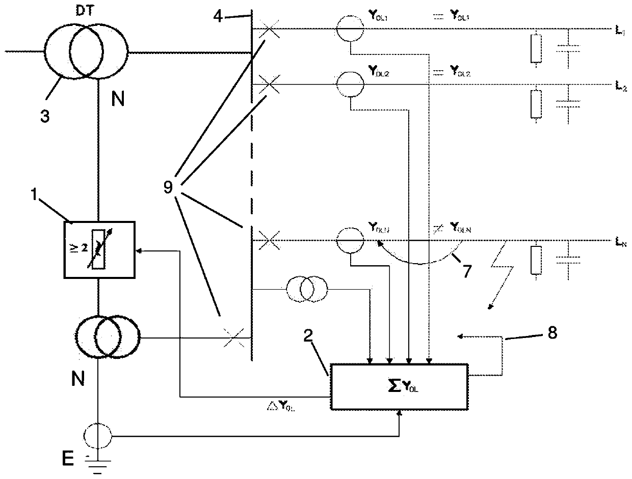
[0014] The remaining problem of generating a voltage that can be controlled in terms of amplitude and phase relative to the supply transformer is firstly solved by arranging two phase-shifting transformers

Method used


Image

  • A device for earth fault current compensation in power networks
  • A device for earth fault current compensation in power networks
  • A device for earth fault current compensation in power networks

Examples


Embodiment Construction

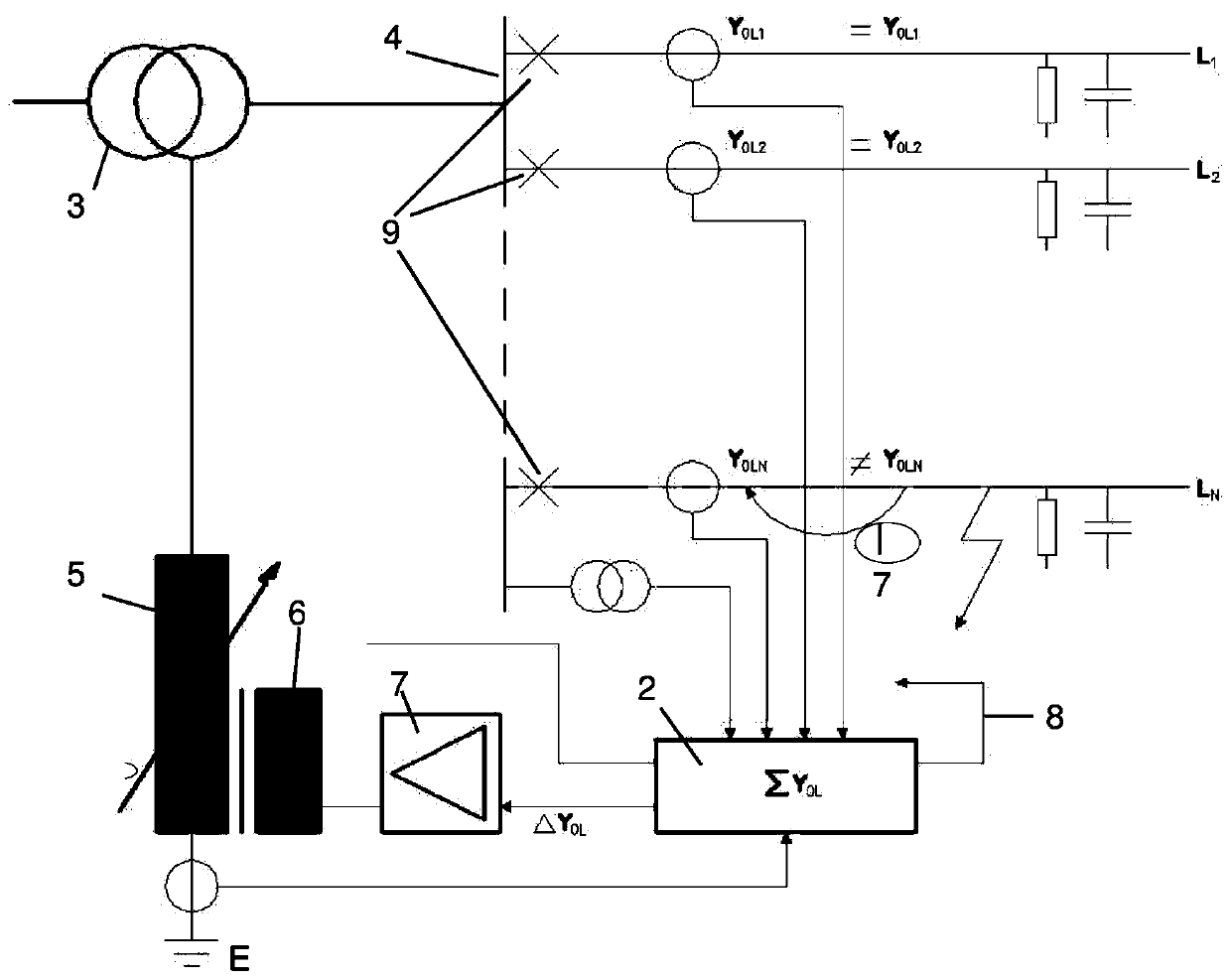
[0041] figure 1 and figure 2 A distribution network with a control and measurement unit 2 for detecting an earth fault and controlling a fault current compensation device is shown. Furthermore, the figure shows a power transformer 3, a bus bar 4, and a plurality of outgoing feeders L each with a circuit breaker 9 on the bus bar 4 1 , L 2 …L N .

[0042] Power transmission is generally achieved through a loop-symmetrical three-phase system. However, even single-phase and two-phase systems (orbits) exist. The common denominator is that the delivery of the load (to the consumer) is driven entirely by the voltage between the two phases. If an error in the form of an insulation fault occurs between these phases, the feeder concerned and all consumers behind it are disconnected by the circuit breaker 9 .

[0043] However, most electrical faults occur between a phase and ground (so-called ground faults). Therefore, the entire system is offset relative to ground. However, th...


PUM


Abstract

A device comprising at least two controllable reactance elements (1) arranged to compensate a single phase-to-earth fault current in a power network with a power transformer (3).The at least two controllable reactance elements (1) are each connected with one side to two different voltages of a three phase voltage source which is synchronous with the power network, and that the reactance elements with their other side are jointly connected to the neutral (N) of the power network or its equivalent.The reactance elements are individually controllable bya control unit (2) designed to control the neutral voltage of the power transformer (3) or its equivalent with respect to amplitude and phase in relation to the power transformer's own voltage system.A method in relation to the device is also disclosed.

Description

technical field [0001] The invention relates to a device for ground fault current compensation according to claim 1, comprising two or more rapidly adjustable reactive elements arranged to compensate ground fault currents in a power network with a power transformer. Furthermore, the invention relates to a method for generating a neutral point voltage in a power network with a power transformer according to claim 7 . Background technique [0002] Today, the transmission of electric power is mainly realized through a symmetrical three-phase voltage system of a cyclo. In order to meet the basic requirements of the system, the generation and consumption of electricity must always be in balance. To facilitate this requirement, large national transmission grids have been created in which all producers and consumers of electricity are interconnected. The connection of these national grids to transnational networks provides further advantages with respect to the basic balancing re...

Claims


Application Information

Patent Timeline
Patent Type & Authority Applications(China)
IPC IPC(8): H02H9/08H02J3/26
CPCH02H9/08H02J3/26H02J3/1828H02J3/1864
Inventor K·温特A·温特H·温特
Owner WINTER BROTHERS
Learn More