Plastic hand shank
A handle and plastic technology, which is applied in the field of plastic bags, can solve the problems of time-consuming, affecting the use, and the insertion strip is easy to go out of the socket, etc., to achieve the effect of improving stability, preventing sliding, and improving static friction
- Summary
- Abstract
- Description
- Claims
- Application Information
AI Technical Summary
Problems solved by technology
Method used
Image

Examples
Embodiment 1
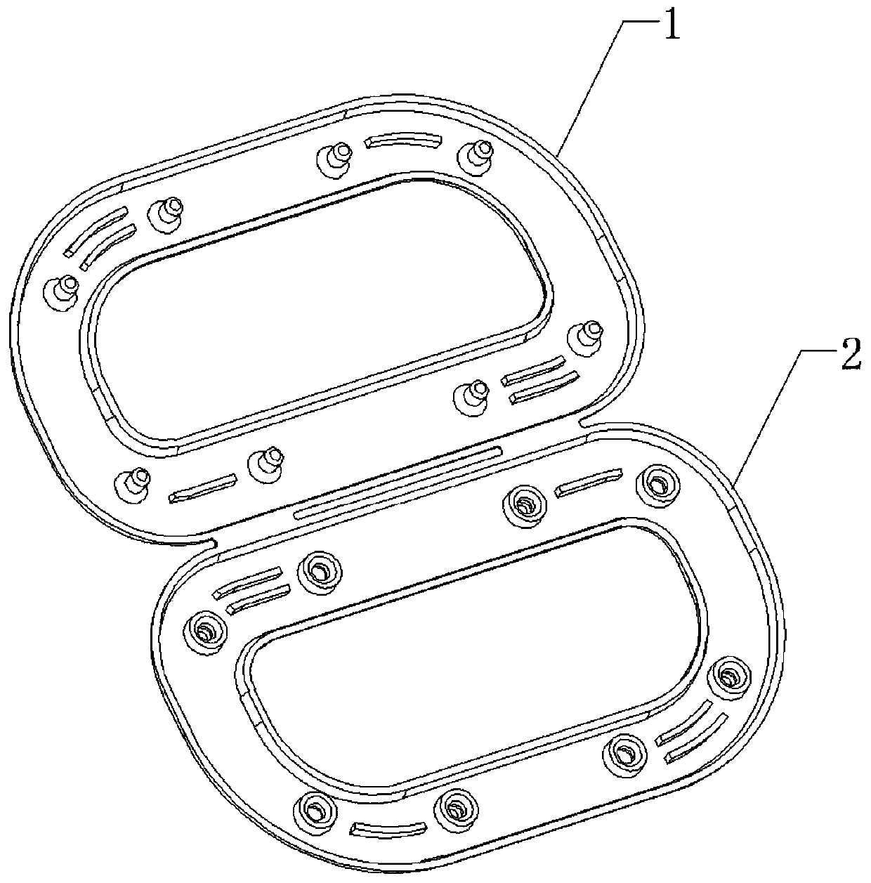
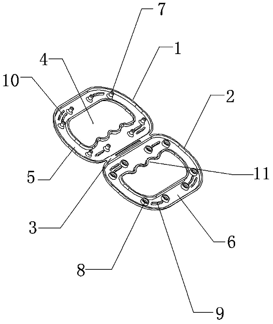
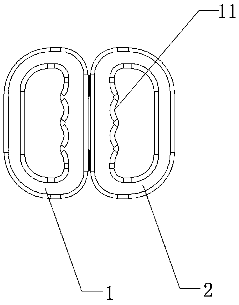
[0022] Embodiment 1: A plastic handle, including a first split body 1, a second split body 2 and a hinged end 3, the hinged end 3 is respectively hinged to the ends of the first split body 1 and the second split body 2, so Both the first split body 1 and the second split body 2 have an opening 4 in the middle for the user to lift, and the inner sides of the first split body 1 and the second split body 2 are respectively provided with hollow first annular grooves 5 With the second annular groove 6, the first annular groove 5 is provided with a plurality of raised positioning columns 7, and the second annular groove 6 is provided with a plurality of protrusions corresponding to the positioning columns 7, and a plurality of The upper end surface of the protruding part is provided with a slot 8 which forms a detachable plug-in fixed fit with the positioning column 7 . The outer surface of the positioning post 7 or the inner surface of the slot 8 is made of elastic rubber material,...
Embodiment 2
[0024] Embodiment 2: A plastic handle, comprising a first split body 1, a second split body 2 and a hinged end 3, the hinged end 3 is respectively hinged to the ends of the first split body 1 and the second split body 2, so Both the first split body 1 and the second split body 2 have an opening 4 in the middle for the user to lift, and the inner sides of the first split body 1 and the second split body 2 are respectively provided with hollow first annular grooves 5 With the second annular groove 6, the first annular groove 5 is provided with a plurality of raised positioning columns 7, and the second annular groove 6 is provided with a plurality of protrusions corresponding to the positioning columns 7, and a plurality of The upper end surface of the protruding part is provided with a slot 8 which forms a detachable plug-in fixed fit with the positioning column 7 . The outer surface of the positioning post 7 or the inner surface of the slot 8 is made of elastic rubber material...
Embodiment 3
[0026] Embodiment 3: A plastic handle, comprising a first split body 1, a second split body 2 and a hinged end 3, the hinged end 3 is respectively hinged to the ends of the first split body 1 and the second split body 2, so Both the first split body 1 and the second split body 2 have an opening 4 in the middle for the user to lift, and the inner sides of the first split body 1 and the second split body 2 are respectively provided with hollow first annular grooves 5 With the second annular groove 6, the first annular groove 5 is provided with a plurality of raised positioning columns 7, and the second annular groove 6 is provided with a plurality of protrusions corresponding to the positioning columns 7, and a plurality of The upper end surface of the protruding part is provided with a slot 8 which forms a detachable plug-in fixed fit with the positioning column 7 . The outer surface of the positioning post 7 or the inner surface of the slot 8 is made of elastic rubber material...
PUM
 Abstract
Description
Claims
Application Information
 - Generate Ideas
- Intellectual Property
- Life Sciences
- Materials
- Tech Scout
- Unparalleled Data Quality
- Higher Quality Content
- 60% Fewer Hallucinations
Browse by: Latest US Patents, China's latest patents, Technical Efficacy Thesaurus, Application Domain, Technology Topic, Popular Technical Reports.
© 2025 PatSnap. All rights reserved.Legal|Privacy policy|Modern Slavery Act Transparency Statement|Sitemap|About US| Contact US: help@patsnap.com