
Parallel steel wire finished rope stretching device with anti-twisting structures and anti-twisting construction method thereof

A tensioning device and anti-rotation technology, which is applied in the field of prestressing, can solve the problems of damaged jacks, safety accidents, and personal injuries of operators.

Pending Publication Date: 2020-01-24
LIUZHOU OVM ENG +1
View PDF0 Cites 3 Cited by
  • Summary
  • Abstract
  • Description
  • Claims
  • Application Information

AI Technical Summary

Problems solved by technology

[0002] At present, the tensioning construction of the finished cable-stayed cables with parallel steel wires is completed by through-hole jacks. For "Finished cable-stayed cables with parallel steel wires", the actual internal steel wires are not parallel, but there is a twist of about 3º Due to the existence of the torsion angle, the stay cable will generate a reverse torsional force when it is stretched. After the torsion force reaches a certain level, it will be released at the tension end, and this force will drive the jacking of the tension jack. The device rotates together, damages the jack, and is also very prone to safety accidents
The above situation is particularly prominent in the installation process of the super-long and super-heavy stay cables used in long-span bridges; at present, most of the on-site construction uses chain hoists to temporarily fix the jack cylinder to avoid the torsion of the cylinder body. When the torsional force is large, the jack piston cannot be avoided. reverse, and even cause personal injury to operators, therefore, it is necessary to propose systematic and effective anti-rotation solutions

Method used


Image

  • Parallel steel wire finished rope stretching device with anti-twisting structures and anti-twisting construction method thereof
  • Parallel steel wire finished rope stretching device with anti-twisting structures and anti-twisting construction method thereof
  • Parallel steel wire finished rope stretching device with anti-twisting structures and anti-twisting construction method thereof

Examples


Embodiment 1

[0047] A parallel steel wire finished cable tensioning device with an anti-twist structure and its anti-twist construction method:

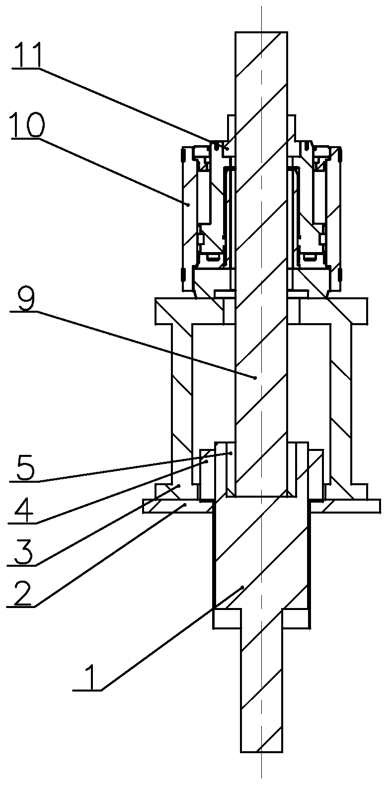
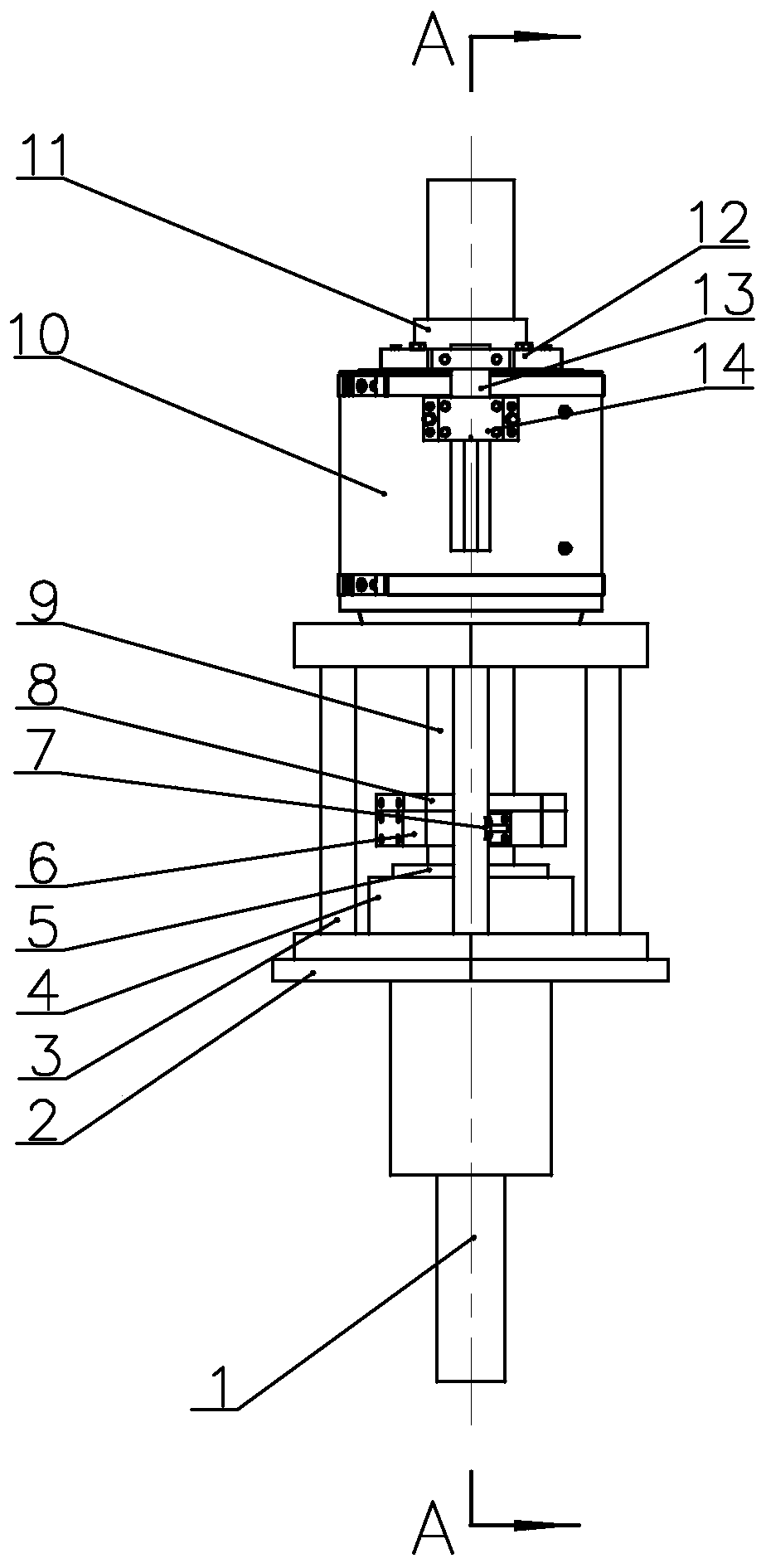
[0048] Such as Figure 1 ~ Figure 3 As shown, a kind of parallel steel wire finished cable tensioning device with anti-torsion structure of the present invention comprises cable anchor head 1, anchor plate 2, support foot 3, working nut 4, inner bushing 5, tension rod 9 , a tensioning device composed of a jack 10 and a tension nut 11, and two anti-rotation structures, anti-rotation structure I and anti-rotation structure II;

[0049] The anti-rotation structure I includes an anti-rotation body 12, an anti-rotation slider 13 and a guide seat 14. The anti-rotation body 12 is fixed on the piston ejection part of the jack 10 by screws, and the guide seat 14 is fixed on the cylinder body of the jack 10 by screws. Above, the anti-rotation slider 13 is located between the anti-rotation body 12 and the guide seat 14, and the anti-rotation slider 13 and t...

Embodiment 2

[0070] A kind of parallel steel wire finished cable tensioning device with anti-twist structure only installed with anti-twist structure I and its anti-twist construction method:

[0071] Such as Figure 4 ~ Figure 5 As shown, the basic structure of the "Parallel Steel Wire Finished Cable Tensioning Device with Anti-Twist Structure" of this embodiment is the same as that of Embodiment 1, and also includes a drag cable anchor head 1, an anchor pad 2, support feet 3, and working nuts. 4. A tensioning device consisting of an inner bushing 5, a tensioning rod 9, a jack 10, and a tensioning nut 11; the difference from Embodiment 1 is that this embodiment only has an anti-twist structure I, and the anti-twist structure The anti-rotation body 12 of I is fixed on the piston ejection part of the jack 10 by screws, the guide seat 14 is fixed on the cylinder body of the jack 10 by screws, and the anti-rotation slider 13 is located between the anti-rotation body 12 and the guide seat 14. ...

Embodiment 3

[0090] A tensioning device for finished parallel steel wire cable with an anti-twist structure and an anti-twist structure only installed with anti-twist structure II and its anti-twist construction method:

[0091] Such as Figure 6 ~ Figure 7 As shown, the basic structure of the "Parallel Steel Wire Finished Cable Tensioning Device with Anti-Twist Structure" of this embodiment is the same as that of Embodiment 1, and also includes a drag cable anchor head 1, an anchor pad 2, support feet 3, and working nuts. 4. A tensioning device consisting of an inner bushing 5, a tensioning rod 9, a jack 10, and a tensioning nut 11; the difference from Embodiment 1 is that this embodiment only has an anti-twist structure II, and the anti-twist structure II includes the Haval nut 6, the thin Haval nut 8 and the anti-rotation arm 7 arranged on the tension rod 9; The anti-rotation torque is greater than the torsional moment generated by the cable. One end of the anti-rotation arm 7 is fixed...


PUM


Abstract

The invention discloses a parallel steel wire finished rope stretching device with anti-twisting structures. The device comprises a stretching device consisting of a pull rope anchor head, an anchor cushion plate, support feet, a working nut, an inner bushing, a stretching rod, a jack and a stretching nut, and one or two anti-twisting structures; the anti-twisting structure I comprises a rotatingstop body, a rotating stop slide block and a guide base; the rotating stop body is fixed at a piston ejecting part of the jack; the guide base is fixed on a cylinder block of the jack; the rotating stop slide block is positioned between the rotating stop body and the guide base, and can move up and down along with a piston of the jack; a Huff nut of the anti-twisting structure II is screwed with athin Huff nut through threads of the stretching rod; one end of the rotating stop arm is fixed on the two sides of the Huff nut through screws; and the other end of the rotating stop arm is joined ona support foot stand column, and can slide along with ascending or descending of the stretching rod. The stretching device is adopted to implement an anti-twisting stretching construction method, canachieve the anti-twisting purpose of tools in the stretching or tensioning construction process of parallel steel wire finished inclined pull ropes, and achieves higher construction efficiency.

Description

technical field [0001] The invention relates to a structural component used in the field of prestressing and a construction method thereof, in particular to a tensioning device for a finished parallel steel wire cable with an anti-twist structure and an anti-twist construction method thereof. Background technique [0002] At present, the tensioning construction of the finished cable-stayed cables with parallel steel wires is completed by through-hole jacks. For "Finished cable-stayed cables with parallel steel wires", the actual internal steel wires are not parallel, but there is a twist of about 3º Due to the existence of the torsion angle, the stay cable will generate a reverse torsional force when it is stretched. After the torsion force reaches a certain level, it will be released at the tension end, and this force will drive the jacking of the tension jack. The device rotates together, damages the jack, and is also very prone to safety accidents. The above situation is...

Claims


Application Information

Patent Timeline
IPC IPC(8): E01D21/00E01D19/16E01D11/04
CPCE01D11/04E01D19/16E01D21/00
Inventor 宁绍锋窦勇芝李居泽韦福堂甘科陈宗泽
Owner LIUZHOU OVM ENG
Learn More