
Plastic bottle stopper production equipment

A technology for producing equipment and plastic bottles, which is applied in the direction of closure plugs, plug feeding, bottle filling, etc., which can solve the problems of easy errors and high equipment costs, and achieve the effects of simple structure, high precision, and cost reduction

Active Publication Date: 2020-01-24
李克文
View PDF7 Cites 9 Cited by
  • Summary
  • Abstract
  • Description
  • Claims
  • Application Information

AI Technical Summary

Problems solved by technology

[0002] After the plastic cork and plastic bottle are produced separately, the plastic bottle cork needs to be placed at the mouth of the plastic bottle. The existing plastic cork installation device is realized by multiple sets of driving components, including the conveying device for conveying plastic bottles, conveying bottle The conveying device for the cork, the negative pressure device for absorbing the cork, the moving device and the pressing device for driving the absorbing cork to move and press fit, and to fix the plastic bottle in the conveying device. In the first stage, the cork is sucked by the negative pressure device, and the sucked cork is moved to the top of the plastic bottle by the moving device, and the plastic bottle is fixed by the fixing device, and finally the cork is pressed into the plastic bottle by the pressing device. In the mouth, on the one hand, multiple sets of driving components work together, and it is necessary to accurately control the intermittent time of the conveying speed of the plastic bottle, the time for absorbing the cork, and the running speed of moving the cork and pressing the cork, which is prone to errors. On the other hand, the equipment cost High, for some small production enterprises, it is not applicable

Method used


Image

  • Plastic bottle stopper production equipment
  • Plastic bottle stopper production equipment
  • Plastic bottle stopper production equipment

Examples


Embodiment Construction

[0017] In order to make the technical means, creative features, goals and effects achieved by the present invention easy to understand, the present invention will be further described below in conjunction with specific embodiments.

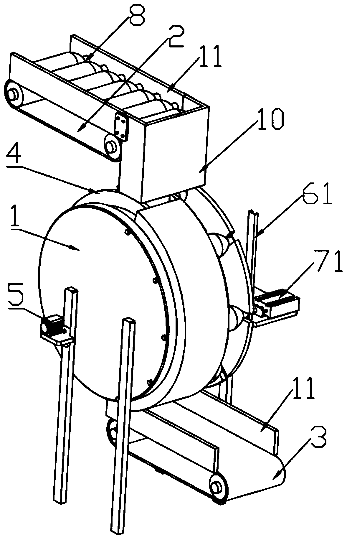
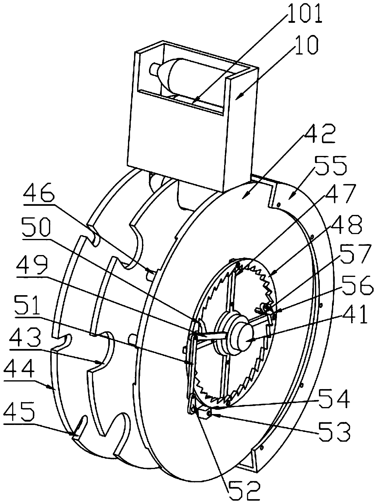
[0018] Such as Figure 1 to Figure 7 As shown, a kind of plastic bottle stopper production equipment, a kind of plastic bottle stopper production equipment, comprises installation frame 1 and plastic bottle feeding assembly 4, and described plastic bottle feeding assembly 4 is arranged vertically and is connected with installation frame 1 in rotation, so A placement frame 10 is provided directly above the plastic bottle feeding assembly 4, a motor 5 is provided on the mounting frame 1, and the output shaft of the motor 5 is connected with a vertical rod 53 in the plastic bottle feeding assembly 4, and the mounting frame 1 1 The side close to the mouth of the plastic bottle 8 is provided with a cork feeding assembly 6 and a pressing assembly 7, and...


PUM


Abstract

The invention discloses plastic bottle stopper production equipment, and relates to the technical field of bottle stopper production and processing. The plastic bottle stopper production equipment includes a mounting frame and a plastic bottle feeding component; a placing frame is arranged over the plastic bottle feeding component, the mounting frame is provided with a motor, and the side, close to bottle openings of plastic bottles, of the mounting frame is provided with a bottle stopper feeding component and a press fit component. The plastic bottle stopper production equipment is simple instructure and convenient to operate. By arranging a ratchet and pawl structure in the plastic bottle feeding component, intermittent rotation of a support plate and a limit plate can be achieved, theplastic bottles are conveyed to the position right ahead the press fit component one by one meanwhile, the support plate drives an annular block to rotate in the rotating process, a tension spring pulls a connection block to slide along a wedge-shaped chute, an inserting plate is inserted into an inserting slot again after leaving the inserting slot, and bottle stoppers can drop one by one. Simultaneous feeding of the plastic bottles and the bottle stoppers can be achieved through one driving element, the cost is reduced, and the feeding accuracy is also high.

Description

technical field [0001] The invention relates to the technical field of production and processing of plastic bottle stoppers, in particular to a production equipment for plastic bottle stoppers. Background technique [0002] After the plastic cork and plastic bottle are produced separately, the plastic bottle cork needs to be placed at the mouth of the plastic bottle. The existing plastic cork installation device is realized by multiple sets of driving components, including the conveying device for conveying plastic bottles, conveying bottle The conveying device for the cork, the negative pressure device for absorbing the cork, the moving device and the pressing device for driving the absorbing cork to move and press fit, and to fix the plastic bottle in the conveying device. In the first stage, the cork is sucked by the negative pressure device, and the sucked cork is moved to the top of the plastic bottle by the moving device, and the plastic bottle is fixed by the fixing d...

Claims


Application Information

Patent Timeline
IPC IPC(8): B67B1/00B65G47/84
CPCB65G47/846B65G2201/0244B67B1/005
Inventor 李克文李继宏
Owner 李克文
Learn More