Superconducting magnetic fluid flowmeter internally provided with grilles

A technology of fluid flow and superconducting magnetism, applied in the application of electromagnetic flowmeter to detect fluid flow, volume/mass flow generated by electromagnetic effect, temperature measurement of moving fluid, etc. Fluid potential, etc.

Pending Publication Date: 2020-01-21
ZHEJIANG UNIV
View PDF7 Cites 0 Cited by
  • Summary
  • Abstract
  • Description
  • Claims
  • Application Information

AI Technical Summary

Problems solved by technology

Existing flowmeter measurement points are generally set on the surface of the pipeline, which can only measure the potential of the fluid on the surface of the pipeline, and cannot test the potential of the fluid at different positions in the pipeline.
Therefore, the fluid data measured by the existing electromagnetic flowmeter cannot fully reflect the flow of metal fluid in the pipeline

Method used


Image

  • Superconducting magnetic fluid flowmeter internally provided with grilles
  • Superconducting magnetic fluid flowmeter internally provided with grilles
  • Superconducting magnetic fluid flowmeter internally provided with grilles

Examples


Embodiment 1

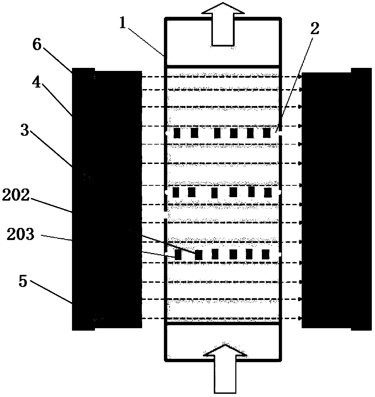
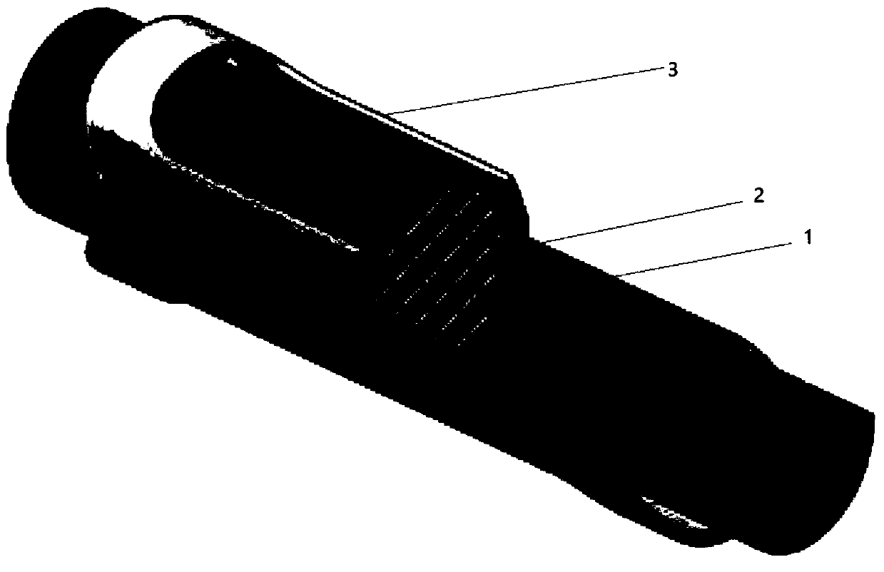
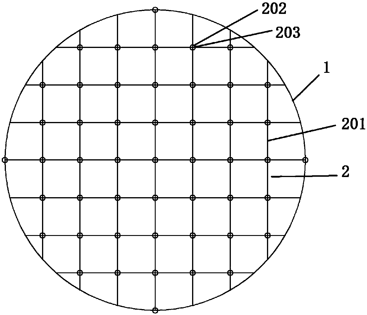
[0028] A superconducting magnetic fluid flowmeter with a built-in grid includes a pipeline 1 and a magnetic field, and the pipeline 1 is perpendicular to the direction of the magnetic field. The pipe is perpendicular to the direction of the magnetic field means that the flow direction of the metal fluid in the pipe is perpendicular to the direction of the magnetic field. The cross-section of the pipe is circular. Take the axial direction of the pipe as the longitudinal direction, and the direction perpendicular to the axial direction as the transverse direction.

[0029] In some embodiments, the duct is polygonal in cross-section.

[0030] grille

[0031] Such as figure 1 with figure 2 As shown, the pipeline 1 is provided with a grid 2, the grid 2 is fixed on the inner wall of the pipeline 1, the plane where the grid 2 is located is perpendicular to the axis of the pipeline 1, and the grid 2 includes a plurality of partitions 201; A plurality of detection electrodes 20...

Embodiment 2

[0040] In this embodiment, except that the magnetic field is generated by superconducting magnetic poles, other structures can adopt the structures described in the above embodiments.

[0041] superconducting pole

[0042] Such as figure 1 As shown, the magnetic field is generated by the superconducting magnetic pole 3, which is in the shape of a cylinder, and the pipeline 1 is located in the cylinder surrounded by the superconducting magnetic pole.

[0043] In some embodiments, superconducting magnetic poles are located on both sides of the tube.

[0044] The superconducting pole 3 is surrounded by a Dewar 4 filled with cooling medium. The Dewar filled with cooling medium maintains the low-temperature state of the superconducting magnetic poles to ensure that the superconducting magnetic poles can generate a magnetic field stably. The cooling medium is liquid nitrogen. In some embodiments, the cooling medium is liquid helium.

[0045] A water jacket 5 is arranged on the ...


PUM


Abstract

The invention provides a superconducting magnetic fluid flowmeter internally provided with grilles. The flowmeter comprises pipelines and a magnetic field, wherein the pipelines are perpendicular to the direction of the magnetic field; the grilles are arranged in the pipelines and fixed at the inner walls of the pipelines, and the plane where the grilles are located is perpendicular to the axes ofthe pipelines; and the grilles comprise a plurality of partitions which are provided with a plurality of detecting electrodes and a plurality of temperature sensors. When metal fluid in the pipelinespasses through the grilles, the detecting electrodes detect the electric potential of the metal fluid at different positions in the pipelines, and the temperature sensors detect the temperature of the metal fluid at different positions in the pipelines. Different positions refer to different depths in the pipelines and different distances to the walls of the pipelines. The superconducting magnetic fluid flowmeter internally provided with the grilles provided by the invention accurately measures the distribution of electric fields and temperature fields of the metal fluid and fully reflects the flow of the metal fluid in the pipelines.

Description

technical field [0001] The invention relates to a flow detection device, in particular to a superconducting magnetic fluid flowmeter with a built-in grid. Background technique [0002] The following background art is provided to help the reader understand the present invention and is not to be admitted as prior art. [0003] Electromagnetic flowmeters are commonly used in the flow measurement of high temperature liquid metals in the industrial field. The electromagnetic flowmeter uses the Hall effect to apply a magnetic field in a direction perpendicular to the axis of the fluid pipeline. When the metal fluid flows in the pipeline and cuts the magnetic force lines, an induced potential is generated in a direction perpendicular to the flow direction and the magnetic force lines. The induced potential is the same as The flow rate of the metal fluid is directly proportional. When the existing electromagnetic flowmeter performs fluid measurement, measuring points are selected ...

Claims


Application Information

Patent Timeline
Patent Type & Authority Applications(China)
IPC IPC(8): G01F1/58G01K13/02
CPCG01F1/58G01K13/02G01K13/026
Inventor 方攸同马吉恩许博文卢琴芬吴立建
Owner ZHEJIANG UNIV
Why Eureka
Try Eureka