Temperature measurement device for radiant tube of rotary kiln
A technology of temperature measuring device and radiant tube, which is applied in the direction of measuring devices, electric devices, and thermometers using electric/magnetic elements that are directly sensitive to heat, can solve the problem of large, tens of millimeters, or even hundreds of millimeters Problems such as displacement, inability to measure the temperature of the radiant tube, and the inability to continue the temperature measurement work
- Summary
- Abstract
- Description
- Claims
- Application Information
AI Technical Summary
Problems solved by technology
Method used
Image
Examples
Embodiment 1
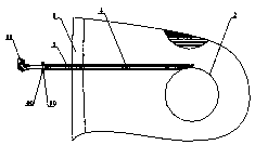
[0022] Such as figure 1 As shown, a temperature measuring device for a rotary kiln radiant tube includes a rotary kiln shell 1, a radiant tube 2, a temperature measuring conduit 3, and a thermocouple 4. The radiant tube 2 is located in the rotary kiln shell 1, and the radiant tubes 2 are parallel to each other. On the center line of the rotary kiln shell 1, the temperature measuring conduit 3 runs through the rotary kiln shell 1, the thermocouple 4 is arranged in the temperature measuring conduit 3, and runs through the temperature measuring conduit 3 along the axis, the temperature measuring conduit 3 and The thermocouples 4 are all perpendicular to the radiation tube 2 , the center line of the temperature measuring conduit 3 is tangent to the outer wall of the radiation tube 2 , and the temperature measuring probes of the thermocouples 4 are in contact with the radiation tube 2 under the guidance of the temperature measuring conduit 3 .
[0023] Preferably, the thermocouple ...
Embodiment 2
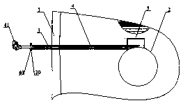
[0028] Such as figure 2 As shown, this embodiment is an improvement on the basis of Embodiment 1. The difference from Embodiment 1 is that the temperature measuring device also includes a thermocouple shield 5, and one side of the thermocouple shield 5 is open, so One side of the opening is arc-shaped, and the arc size of the arc is consistent with the arc size of the outer wall of the radiant tube 2. The end of the temperature-measuring conduit 3 extending into the kiln body extends into the thermocouple shield 5, and is connected with the thermocouple shield 5. The thermocouple shield 5 is fixed together, and the arc surface of the thermocouple shield 5 is closely attached to the outer wall of the radiation tube 2 to protect the thermocouple 4 temperature measuring probe. The thermocouple shield 5 The environment where the thermocouple probe is located is consistent with the surface temperature of the radiation tube here, and the accuracy of temperature measurement is guara...
Embodiment 3
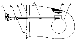
[0030] Such as image 3 As shown, this embodiment is an improvement made on the basis of embodiment 2. The difference from embodiment 2 is that the thermocouple 4 is provided with a junction box at the outer end of the rotary kiln shell 1, and at the One end of the box 41 is provided with an external thread 42 , and one end of the temperature measuring conduit 3 outside the rotary kiln shell 1 is provided with an internal thread 33 corresponding to the external thread 42 .
PUM
 Abstract
Description
Claims
Application Information
 - R&D
- Intellectual Property
- Life Sciences
- Materials
- Tech Scout
- Unparalleled Data Quality
- Higher Quality Content
- 60% Fewer Hallucinations
Browse by: Latest US Patents, China's latest patents, Technical Efficacy Thesaurus, Application Domain, Technology Topic, Popular Technical Reports.
© 2025 PatSnap. All rights reserved.Legal|Privacy policy|Modern Slavery Act Transparency Statement|Sitemap|About US| Contact US: help@patsnap.com


