Multifunctional flow experiment device

An experimental device and multi-functional technology, which is applied in the direction of detecting fluid flow and volume/mass flow generated by electromagnetic effects with electromagnetic flowmeter, and can solve the problem of not fully reflecting the flow of metal fluid

Inactive Publication Date: 2020-01-21
ZHEJIANG UNIV
View PDF3 Cites 0 Cited by
  • Summary
  • Abstract
  • Description
  • Claims
  • Application Information

AI Technical Summary

Problems solved by technology

Therefore, the fluid data measured by the existing electromagnetic flowmeter cannot fully reflect the flow of metal fluid in the pipeline

Method used


Image

  • Multifunctional flow experiment device
  • Multifunctional flow experiment device

Examples


Embodiment 1

[0027] Detection electrode

[0028] A multifunctional flow experiment device includes a pipeline and a magnetic field, the pipeline is perpendicular to the direction of the magnetic field, and the magnetic field covers the entire pipeline. The pipe is perpendicular to the direction of the magnetic field means that the flow direction of the fluid in the pipe is perpendicular to the direction of the magnetic field. The cross-section of the duct is rectangular.

[0029] like figure 1 As shown, there are 6 detection units distributed on the wall of the pipeline 2, each detection unit has 12 detection electrodes 3, each detection unit corresponds to a cross section of a pipeline, one end of the detection electrode 3 is in contact with the conductive fluid in the pipeline, and the other is in contact with the conductive fluid in the pipeline. One end is exposed to the pipeline; the potential of all detection electrodes represents the electric field distribution of the conductive f...

Embodiment 2

[0039] In this embodiment, except that the pipeline is provided with two pressurized electrodes, other structures can adopt the structure described in Embodiment 1.

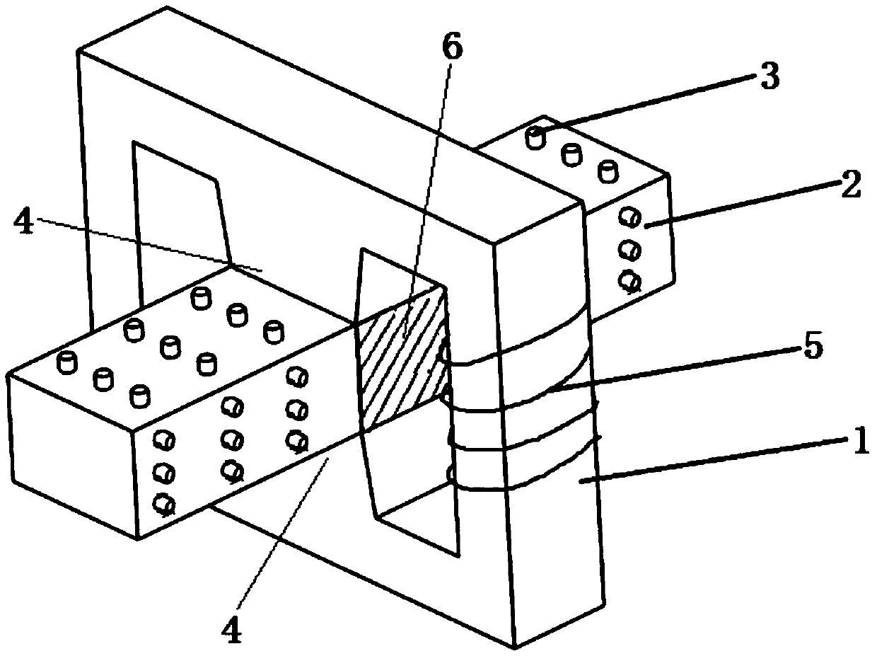
[0040] like figure 2 As shown, the pipeline 2 is provided with two pressurized electrodes 6, the pressurized electrodes are connected to the power supply, and the conductive fluid between the pressurized electrodes is used as a conductor connecting the two pressurized electrodes; the direction of the current between the pressurized electrodes and the direction of the magnetic field Vertically, the direction of current flow between two pressurized electrodes is perpendicular to the direction of flow of the conductive fluid. After the pressurized electrodes are energized, an electric field is generated in the conductive fluid between the pressurized electrodes, and the electric field makes the ions in the conductive fluid move in a direction, and the moving direction is perpendicular to the direction of the magnet...


PUM


Abstract

The invention discloses a multifunctional flow experiment device. The multifunctional flow experiment device includes a pipeline and a magnetic field, and the pipeline is perpendicular to the direction of the magnetic field. The perpendicularity between the pipeline and the direction of the magnetic field means that the flow direction of fluid in the pipeline is perpendicular to the direction of the magnetic field. A plurality of detection units are distributed on the wall of the pipeline; each detection unit is provided with a plurality of detection electrodes; each detection unit correspondsto a cross section of the pipeline; one end of each detection electrode is in contact with the conductive fluid in the pipeline, and the other end is exposed outside the pipeline; and the potentialsof all detection electrodes characterize the electric field distribution of the conductive fluid in the pipeline. The multifunctional flow experiment device provided by the invention can measure the electric field distribution and flow field distribution of each point in the conductive fluid, thereby fully reflecting the flow condition of the metal fluid in the pipeline.

Description

technical field [0001] The invention relates to a multifunctional flow experiment device. Background technique [0002] The following background art is provided to help the reader understand the present invention and is not to be admitted as prior art. [0003] Measuring fluid velocity in pipelines is an important technology in industrial production. A flow meter is a common device for measuring the flow rate of a fluid. Some flow meters have an impeller, and the flow rate of the fluid can be measured by counting the speed and number of revolutions of the impeller. However, due to the large contact area between the impeller and the fluid, it is easy to be corroded, so it is not suitable for measuring the flow rate of the corrosive fluid. The magnetic permeability flowmeter uses the Hall effect to apply a magnetic field in the direction perpendicular to the axial direction of the pipeline. When the conductive fluid flows in the pipeline and cuts the magnetic force lines in...

Claims


Application Information

Patent Timeline
IPC IPC(8): G01F1/58
CPCG01F1/58
Inventor 马吉恩许博文方攸同卢琴芬吴立建
Owner ZHEJIANG UNIV
Why Eureka
Try Eureka