
Self-cleaning multi-stage pressure-reducing regulating valve

A pressure-reducing adjustment and self-cleaning technology, which is applied to valve details, valve devices, sliding valves, etc., can solve the problems that the blockage cannot be automatically cleared, the performance of the valve is reduced, and the number of bending times is too high, so as to achieve compact structure, improve performance and The effect of long service life and convenient operation

Active Publication Date: 2021-05-28
CHINA SHIP SCIENTIFIC RESEARCH CENTER (THE 702 INSTITUTE OF CHINA SHIPBUILDING INDUSTRY CORPORATION)
View PDF0 Cites 0 Cited by
  • Summary
  • Abstract
  • Description
  • Claims
  • Application Information

AI Technical Summary

Problems solved by technology

These two existing multi-stage pressure-relief valves, because the size of a single flow hole or flow channel on the sleeve is small, and the flow is circuitous and bends many times during the flow process, there is a large gap in the flow hole or flow channel. Risk of blockage, and once blockage occurs, it cannot be cleared automatically, which will seriously reduce the performance of the valve and even cause the valve to fail

Method used


Image

  • Self-cleaning multi-stage pressure-reducing regulating valve
  • Self-cleaning multi-stage pressure-reducing regulating valve
  • Self-cleaning multi-stage pressure-reducing regulating valve

Examples


Embodiment Construction

[0035] The specific implementation manner of the present invention will be described below in conjunction with the accompanying drawings.

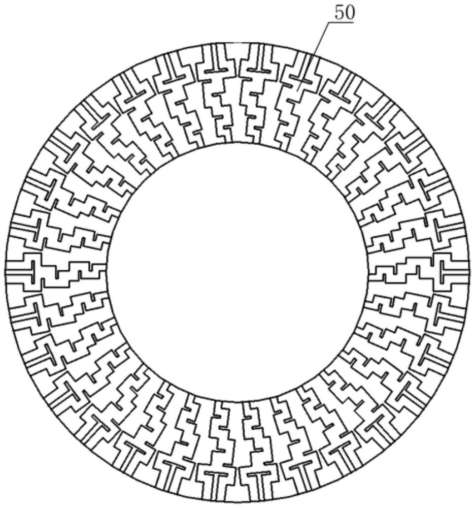
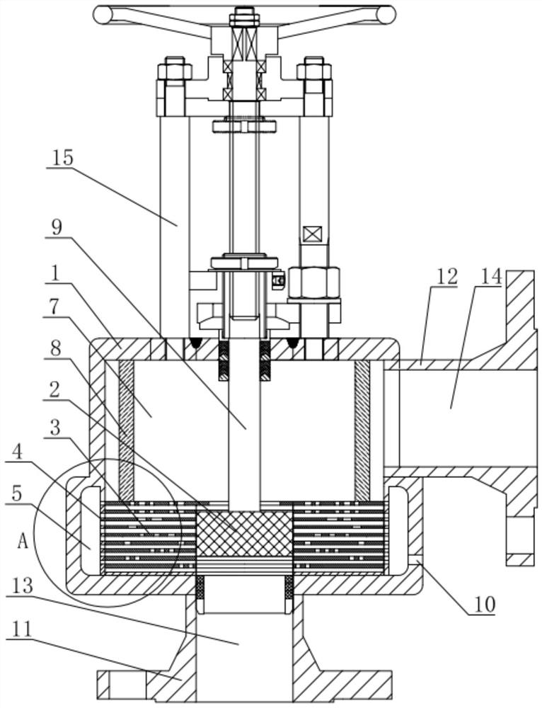
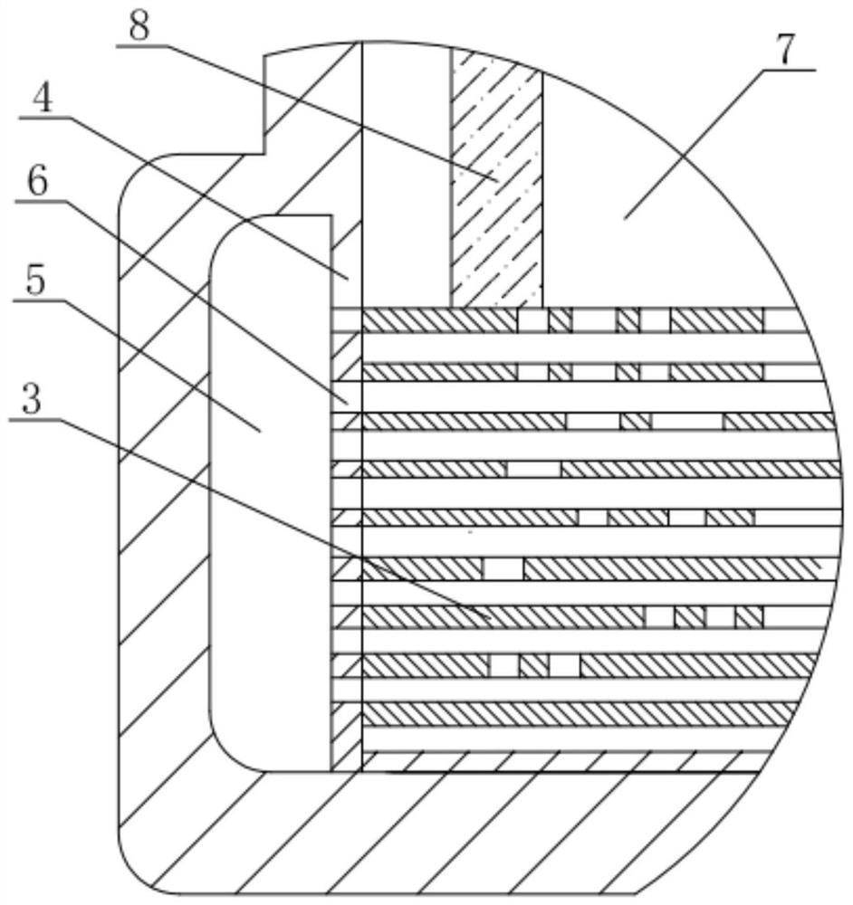
[0036] like figure 2 and image 3 As shown, the self-cleaning multi-stage pressure-reducing regulating valve of this embodiment includes a hollow valve body 1, a sleeve 3 is installed on the inner bottom surface of the valve body 1, and a valve body 1 located outside the outer peripheral surface of the sleeve 3 is provided with Interlayer 4, a sewage discharge chamber 5 is formed between the interlayer 4 and the inner wall of the valve body 1, and a sewage discharge groove 6 is arranged on the interlayer 4; a valve core 2 is installed in the middle of the sleeve 3;

[0037] The structure of the sleeve 3 is as follows: it includes multiple discs 32 stacked at intervals, each disc 32 has a plurality of through holes 35 for fluid flow;

[0038] The valve core 2 drives the sleeve 3 to move, so that the discs 32 or the intervals between the ...


PUM


Abstract

The invention relates to a self-cleaning multi-stage pressure-reducing regulating valve, which comprises a hollow valve body inside, a sleeve is installed on the bottom surface of the valve body, and an interlayer is arranged in the valve body outside the outer peripheral surface of the sleeve, between the interlayer and the inner wall surface of the valve body A sewage discharge chamber is formed, and a sewage discharge groove is arranged on the interlayer; a valve core is installed in the middle of the sleeve; the sleeve includes multiple discs stacked at intervals, and a plurality of through holes for fluid flow are opened on each disc, and the fluid flows through each disc. The friction between the through hole and the flow channel between layers realizes the layer-by-layer pressure reduction; the valve stem drives the valve core to move to align with different discs to adjust the pressure reduction coefficient; when the valve core moves up, it finally drives the sleeve to move, making the disc The gap between the sheets is aligned with the sewage groove, so that the fluid flows through the interlayer flow channel and the sewage groove to the sewage chamber to realize self-cleaning. The present invention realizes the self-cleaning of the regulating valve while realizing multi-stage pressure reduction, and greatly improves its service life and performance.

Description

technical field [0001] The invention relates to the technical field of valves, in particular to a self-cleaning multi-stage decompression regulating valve. Background technique [0002] Regulating valves are commonly used in pipelines to regulate the flow of fluid in the pipeline. For applications where there is a large difference in fluid pressure before and after adjustment, a multi-stage pressure relief valve is usually used to gradually reduce the pressure of the fluid by using the multi-stage structure of the sleeve in the pressure relief valve. [0003] In the prior art, the sleeve of the multi-stage pressure-reducing valve mainly has two structural forms, one is a structure in which several coaxial sleeves are arranged outside the valve core, and a plurality of holes are arranged on each sleeve, stacking multiple multi-level sleeve for multi-stage decompression; the other is a labyrinth disc stacked structure, which processes multi-stage radial 90-degree bending chan...

Claims


Application Information

Patent Timeline
Patent Type & Authority Patents(China)
IPC IPC(8): F16K47/08F16K3/30F16K27/04
CPCF16K3/30F16K27/04F16K47/08
Inventor 梁赟何涛郝夏影王秋波
Owner CHINA SHIP SCIENTIFIC RESEARCH CENTER (THE 702 INSTITUTE OF CHINA SHIPBUILDING INDUSTRY CORPORATION)
Learn More