Extension pipe for vacuum cleaner

A technology for vacuum cleaners and extension tubes, which is applied in the field of extension tubes for vacuum cleaners. It can solve the problems of dead corners, heavy weight of extension rods, and poor appearance aesthetics, and achieve the effects of reducing the difficulty of injection molding, prolonging the service life, and facilitating rapid passage.

Active Publication Date: 2020-01-21
尚科宁家(香港)股份有限公司
View PDF18 Cites 1 Cited by
  • Summary
  • Abstract
  • Description
  • Claims
  • Application Information

AI Technical Summary

Problems solved by technology

[0003] In the prior art, the axial through hole for the power supply line is generally formed inside the extension tube. From the perspective of the cross section, the axial through hole will occupy the inner hole space inside the extension tube for air flow, resulting in the shape of the inner hole of the extension tube It becomes irregular, and the garbage is easily affected when it passes through the extension tube, and it is easy to form a hygienic dead angle on the partition separating the axial through hole and the inner hole, which further affects the dust collection effect
In addition, most of the existing extension rods are integrally injection-molded with plastic parts. Due to the need for injection-molded wiring channels, molding is difficult, and the obtained extension rods are heavy, with poor appearance and poor overall user experience.

Method used


Image

  • Extension pipe for vacuum cleaner
  • Extension pipe for vacuum cleaner
  • Extension pipe for vacuum cleaner

Examples


Embodiment Construction

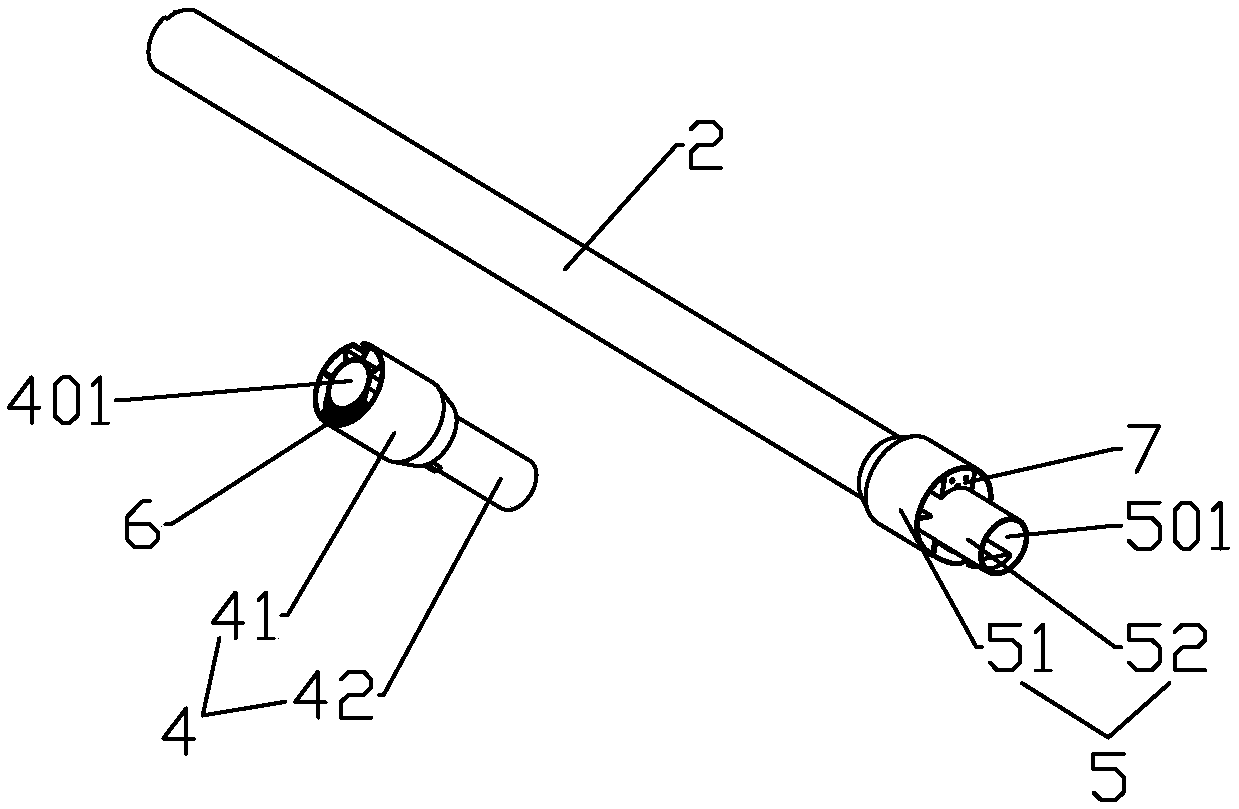
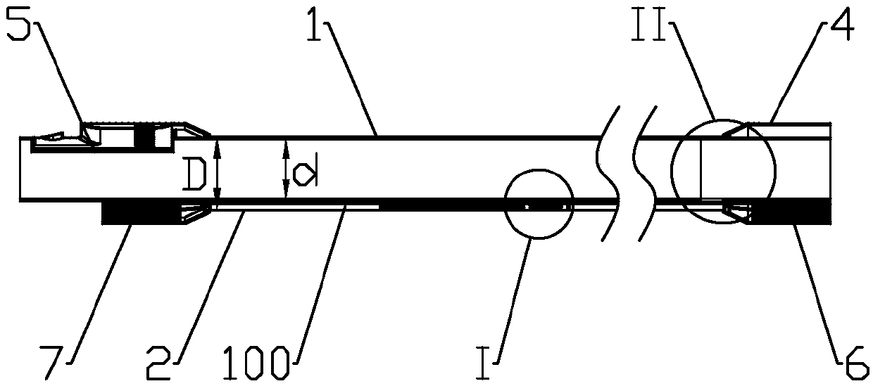
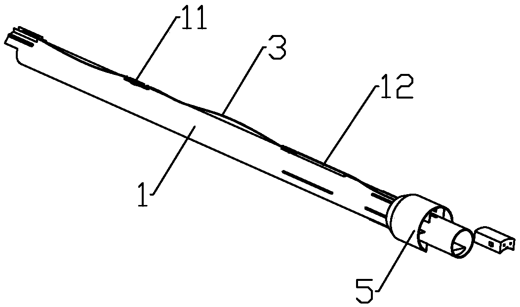
[0023] The invention provides an extension tube for a vacuum cleaner, which combines figure 1 , 2 See, including the inner tube 1, the outer tube 2 and the electric wire 3, the outer tube 2 is set on the outside of the inner tube 1, and the two ends of the inner tube 1 are respectively provided with a first connector 4 and a second connector 5, the first connector 4 and at least one of the second connector 5 and the inner tube 1 or the outer tube 2 are separate structural members, the first connector 4 includes a first communication hole 401 that is docked with the inner tube 1, and the hole 401 is connected to the inner cavity of the inner tube 1 The second connection head 5 includes a second communication hole 501 that is docked with the inner tube 1, and the hole 501 is also communicated with the inner cavity of the inner tube 1. The first connection head 4 and the second connection head 5 are provided for fixing the outer The tube 2 makes the outer tube 2 limit structure ...


PUM


Abstract

The invention discloses an extension pipe for a vacuum cleaner, and belongs to the field of electrical appliances. The problem of large influences on an inner pipe due to arrangement of an electric wire on an extension pipe is solved. According to the technical scheme, the extension pipe mainly includes an inner pipe, an outer pipe and an electric wire, and the outer pipe sleeves the outside of the inner pipe; a first connector and a second connector are arranged at the two ends of the inner pipe correspondingly, the first connector includes a first communication hole in butt joint with the inner pipe, and the second connector includes a second communication hole in butt joint with the inner pipe; and the first connector and the second connector fix the outer pipe so that a wiring channelfor wiring the electric wire is formed between the outer pipe and the inner pipe, the first connector is provided with a first wiring terminal, the second connector is provided with a second wiring terminal, one end of the electric wire is connected to the first wiring terminal, and the other end of the electric wire is connected to the second wiring terminal. The extension pipe is mainly used forfacilitating the assembly of the extension pipe and reducing the influences of the arrangement of the electric wire on the inner pipe.

Description

technical field [0001] The invention relates to electrical appliances, in particular to an extension tube for a vacuum cleaner. Background technique [0002] Most of the existing vacuum cleaners are equipped with extension tubes for the convenience of users. When cleaning the ground or high places, the extension tubes can be connected between the main body of the vacuum cleaner and the suction head of the vacuum cleaner to increase the working radius of the vacuum cleaner. Because most of the existing vacuum cleaner suction heads are also provided with a motor that drives the roller brush, the main body of the vacuum cleaner needs to supply power to the motor. After connecting the extension tube, the motor needs to be connected to the power supply through the extension tube. [0003] In the prior art, the axial through hole for the power supply line is generally formed inside the extension tube. From the perspective of the cross section, the axial through hole will occupy t...

Claims


Application Information

Patent Timeline
Patent Type & Authority Applications(China)
IPC IPC(8): A47L9/00
CPCA47L9/244A47L9/248
Inventor 王旭宁
Owner 尚科宁家(香港)股份有限公司
Why Eureka
Try Eureka