Air conditioner system

A technology for air conditioners and indoor units, applied in transmission systems, baseband systems, digital transmission systems, etc., can solve problems such as low speed, and achieve the effect of high-speed data transmission

Active Publication Date: 2022-02-11
HITACHI JOHNSON CONTROLS AIR CONDITIONING INC
View PDF7 Cites 0 Cited by
  • Summary
  • Abstract
  • Description
  • Claims
  • Application Information

AI Technical Summary

Problems solved by technology

[0002] In the past, the communication network of the air conditioner system was mainly used to transmit a small amount of information such as the operating status of the outdoor unit and indoor unit, and control commands, so it was slower than Ethernet (registered trademark) such as 100BASE-T and optical fiber communication.

Method used


Image

  • Air conditioner system
  • Air conditioner system
  • Air conditioner system

Examples


no. 1 approach

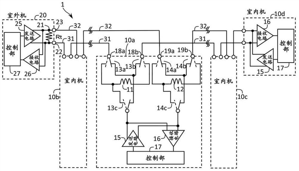
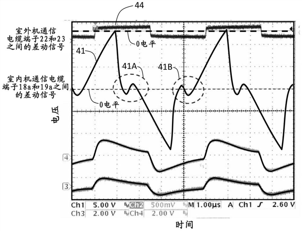
[0029] figure 1 It is a figure which shows the communication system of the air conditioner system 1 which concerns on 1st Embodiment of this invention.

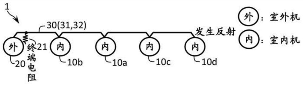
[0030] The air conditioner system 1 includes an air conditioner including indoor units 10 a , 10 b , 10 c , and 10 d , an outdoor unit 20 , and communication cables 31 , 32 . The communication cables 31, 32 carry out serial data transmission by means of differential signals, so vinyl-coated twin-core cables or twisted-pair cables are used. The indoor units 10a, 10b, 10c, and 10d and the outdoor unit 20 are connected in chain (also referred to as through wiring) through communication cables 31 and 32 to transmit and receive the same signal, and a so-called serial bus system is adopted. Communication cables 31 and 32 correspond to transmission lines.

[0031] The indoor unit 10a includes inductors 11, 12, communication cable terminals 18a, 18b, transmission path switches 13a, 13b, 13c, communication cable terminals 19a, 19b, ...

no. 2 approach

[0088] Next, an air conditioner system 100 according to a second embodiment of the present invention will be described.

[0089] Image 6 is a diagram showing a communication network of the air conditioner system 100 .

[0090] exist Image 6 In , the state where the outdoor unit and the indoor unit are connected to a free communication network topology based on a hybrid of chain wiring and star branch wiring is shown.

[0091] The air conditioner system 1 includes outdoor units 20a, 20b, indoor units 10a-10i, communication cables 30a, 30b, 30c connecting the outdoor unit 20a and the indoor units 10a-10i, and a terminal resistor 21 connected to the outdoor unit 20a. When there are two outdoor units 20a and 20b in the communication network, the terminating resistor 21 is connected to either one in advance. In this air conditioner system 100, the indoor unit 20a is in charge of the refrigerant system for the indoor units 10a to 10d, 10e, 10f, and 10i, and the other outdoor un...


PUM


Abstract

The present invention provides technology enabling high-speed data transmission in communication between a plurality of outdoor units and indoor units connected to a free communication network topology. The indoor unit (10a) is provided with: a communication cable terminal (18a) connected to the communication cable (31) connected to the indoor unit (10b), and a communication cable terminal (18b) connected to the communication cable (31) connected to the indoor unit 10c , a transmission path switch (13a) connected to the communication cable terminal (18a), a transmission path switch (13b) connected to the communication cable terminal (18b), connected between the transmission path switch (13a) and the transmission path switch (13b) inductance(11). Each indoor control unit (15) switches the transmission path switch (13a) and the transmission path switch (13b) to the state of short-circuiting the communication cable terminal (18a) and the communication cable terminal (18b), and switches the communication cable terminal (18a) and The state where the communication cable terminal (18b) is connected via the delay element (11).

Description

technical field [0001] The present invention relates to an air conditioner system that is wired between devices and controlled through communication. Background technique [0002] In the past, the communication network of the air conditioner system was mainly used to transmit a small amount of information such as the operating status of the outdoor unit and indoor unit and control commands, so it was slower than Ethernet (registered trademark) such as 100BASE-T and optical fiber communication. In addition, long distances between devices require a large amount of wiring, so instead of using a modulated carrier method using a high-frequency cable such as a coaxial cable, cost reduction is achieved by using a baseband transmission method. [0003] On the other hand, in recent years, with the complexity of facilities and equipment and the diversification of transmission information, it is required to support high-speed serial data transmission. [0004] It is known that when se...

Claims


Application Information

Patent Timeline
Patent Type & Authority Patents(China)
IPC IPC(8): H04L25/02F24F11/88
CPCF24F11/88F24F11/54F24F11/50H04L25/0298H04L25/0272
Inventor 杉山由一町田芳广山本裕二齐藤慎也
Owner HITACHI JOHNSON CONTROLS AIR CONDITIONING INC
Why Eureka
Try Eureka