Transmitting coil drive circuit and method

A technology of transmitting coils and driving circuits, applied in the field of transmitting coil driving circuits, can solve the problems of different driving capabilities, equipment may not be able to achieve close effects, etc., to achieve the effect of ensuring the magnetic field strength and detection accuracy, and making up for product differences.

Active Publication Date: 2020-01-17
TECHIK INSTR SHANGHAI
View PDF10 Cites 1 Cited by
  • Summary
  • Abstract
  • Description
  • Claims
  • Application Information

AI Technical Summary

Problems solved by technology

[0003] An important part of the metal detector is the load transmitting coil and the driving circuit used to drive the load transmitting coil, but the driving ability of the circuit with different output impedance is different for different loads. If the load changes, the original equipment may not be able to get close to

Method used


Image

  • Transmitting coil drive circuit and method
  • Transmitting coil drive circuit and method
  • Transmitting coil drive circuit and method

Examples


Embodiment Construction

[0025] The present invention will be described in detail below in conjunction with the accompanying drawings and specific embodiments. This embodiment is implemented on the premise of the technical solution of the present invention, and detailed implementation and specific operation process are provided, but the protection scope of the present invention is not limited to the following embodiments.

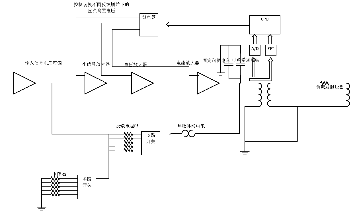
[0026] A transmit coil drive circuit such as figure 1 As shown, it includes the acquisition control debugging module, amplification module, and feedback circuit module. One end of the feedback module is connected to the transmitting module, and the other end is connected to the input end of the amplification module. The input end of the amplification module is also connected to the acquisition control debugging module, and the output end Connect to the transmitter module;

[0027] The application can be applied to different load coils. When the load transmitting coil is changed, t...


PUM


Abstract

The invention relates to a transmitting coil drive circuit and method. The drive circuit includes a collection control debugging module, an amplification module, and a feedback circuit module. One endof the feedback module is connected to a transmitting module, and the other end is connected to an input end of the amplification module. The input end of the amplification module is also connected to the collection control debugging module, and an output end is connected to the transmitting module. When a load transmitting coil changes, the collection control debugging module controls a coil resonance voltage by adjusting the feedback module, to ensure magnetic field intensity and detection accuracy. Compared with the prior art, the invention has the advantages such as being capable to compensate to a certain extent for product differences caused by different coil crafts.

Description

technical field [0001] The invention relates to the field of metal detectors, in particular to a transmitting coil driving circuit and method. Background technique [0002] Metal detectors are used in all walks of life, especially for detecting metal foreign objects mixed in the production process of food, medicine, cosmetics, textiles and so on. The principle is a central transmitting coil and two equal receiving coils, which are housed in a detection head. The oscillator emits a high-frequency magnetic field through the middle transmitting coil, which is connected to two receiving coils, but the polarity is opposite. When the magnetic field is not disturbed by the outside world, the voltage output signals generated by them cancel each other out. Once metal impurities enter the magnetic field area, this balance will be destroyed, and the induced voltage of the two receiving coils cannot be offset. The induced voltage that has not been offset is amplified by the control sys...

Claims


Application Information

Patent Timeline
Patent Type & Authority Applications(China)
IPC IPC(8): G01V3/10
CPCG01V3/10
Inventor 殷星牟翔
Owner TECHIK INSTR SHANGHAI
Why Eureka
Try Eureka