
Petroleum mass flow detection system and detection method thereof

A mass flow and detection system technology, which is applied in the direction of mass flow measurement devices, measurement devices, material inspection products, etc., can solve the problems of inaccurate measurement of sample oil flow, uneven inner wall of pipeline, uneven flow velocity, etc., and improve detection accuracy and accuracy, convenient detection, and simple operation

Inactive Publication Date: 2020-01-17
JILIN UNIV
View PDF7 Cites 1 Cited by
  • Summary
  • Abstract
  • Description
  • Claims
  • Application Information

AI Technical Summary

Problems solved by technology

However, the above method is only suitable for the ideal situation where the liquid sample is always filled with the pipeline and the flow rate is moderate, which has certain limitations.
1. When the sample is full of pipelines but the flow rate is fast and slow or turbulent, the current flow rate of the sample oil cannot be accurately measured; 2. When the oil flow rate is too small to completely fill the entire pipeline, the sample oil cannot be accurately measured Current flow rate; 3. Due to the particularity of the sample oil, which is viscous and easy to adhere to the surrounding wall of the pipe, the inner wall of the pipe is not smooth, and the oil will be affected by it during the flow process. Uniformity makes it impossible to accurately measure the current flow rate of the sample oil
The above factors will lead to systematic measurement errors in the detection of oil "mass flow", so the present invention proposes a new system for measuring oil "mass flow", which can effectively correct the above-mentioned system errors, so that the detection of oil "mass flow" The accuracy has been greatly improved ["mass flow" - the flow of pure petroleum (excluding water) per unit time]

Method used

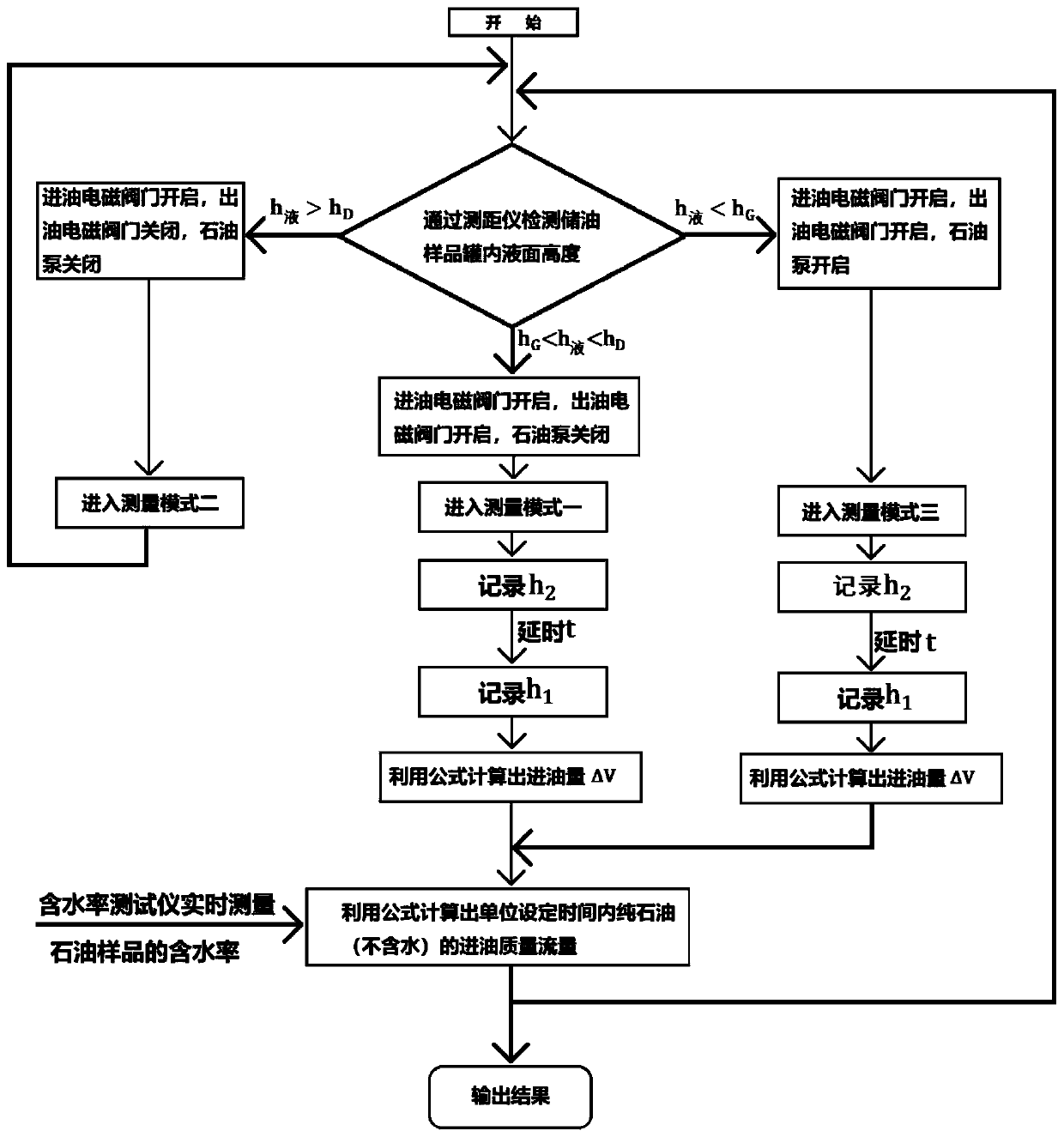

Image

  • Petroleum mass flow detection system and detection method thereof
  • Petroleum mass flow detection system and detection method thereof

Examples


Embodiment Construction

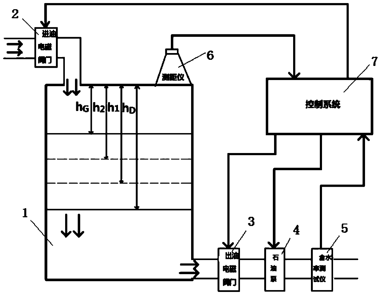
[0021] Such as figure 1 As shown, the oil mass flow detection system of the present invention includes an oil inlet electromagnetic valve 2, an oil outlet electromagnetic valve 3, a petroleum pump 4, a water content tester 5, a range finder 6, and a control system 7; the oil inlet electromagnetic valve 2 is installed on the oil inlet pipe at the top of the oil storage sample tank 1, and the oil outlet electromagnetic valve 3, the oil pump 4 and the water content tester 5 are installed on the oil outlet pipe at the bottom of the oil storage sample tank 1; The top of the oil sample tank 1; the signal output terminals of the rangefinder 6 and the water content tester 5 are connected to the data input terminal of the control system 7, and the three control signal output terminals of the control system 7 are respectively connected to the oil inlet solenoid valve 2 and the oil outlet valve. The control end of the electromagnetic valve 3 and the oil pump 4.

[0022] The oil inlet so...


PUM


Abstract

The invention relates to a petroleum mass flow detection system and a detection method thereof. An oil input electromagnetic valve of the system is mounted on an oil input pipe located at the top of an oil storage sample tank. An oil output electromagnetic valve, a petroleum pump and a water content tester are mounted on an oil output pipe of the bottom of the oil storage sample tank. A rangefinder is mounted on the top of the oil storage sample tank. Signal output ends of the rangefinder and the water content tester are connected with data input ends of a control system. 3 control signal output ends of the control system are respectively connected with and control ends of the oil input electromagnetic valve, the oil output electromagnetic valve and the petroleum pump. According to the system, flow detection precision and accuracy of detected sample petroleum are improved, detection errors brought by different factors that the sample petroleum does not fill an entire pipeline, flow velocity is uneven, and adhesion and obstruction occur can be effectively solved, operation is simple, and the sample petroleum can be accurately, reliably, quickly and conveniently detected on site in real time.

Description

technical field [0001] The invention belongs to the technical field of petroleum flow detection, and relates to a petroleum mass flow detection system and a detection method thereof. Background technique [0002] At present, real-time detection methods for oil production at home and abroad mostly use a series of detection, calculation, and derivation of the flow rate and water content of sample oil in the oil pipeline, so as to obtain the quality of pure oil contained in the sample oil in the pipeline. However, the above method is only suitable for the ideal condition that the liquid sample is always filled with the pipeline and the flow rate is moderate, and has certain limitations. 1. When the sample is full of pipelines but the flow rate is fast and slow or turbulent, the current flow rate of the sample oil cannot be accurately measured; 2. When the oil flow rate is too small to completely fill the entire pipeline, the sample oil cannot be accurately measured Current flo...

Claims


Application Information

Patent Timeline
Patent Type & Authority Applications(China)
IPC IPC(8): G01F1/76G01N33/28
CPCG01F1/76G01N33/2847
Inventor 张涛马敬韩冰
Owner JILIN UNIV
Learn More