
Machine vision and scanning detection device and working method thereof

A technology of scanning detection and machine vision, which is applied in the field of part size detection, can solve the problems of inconvenient positioning and pick-and-place, low scanning detection efficiency, and narrow application range, etc., to achieve lower precision requirements, broaden adaptation and general performance, and wide application range Effect

Pending Publication Date: 2020-01-17
三明图灵智能科技有限公司
View PDF0 Cites 5 Cited by
  • Summary
  • Abstract
  • Description
  • Claims
  • Application Information

AI Technical Summary

Problems solved by technology

[0008] In view of the deficiencies in the prior art, the technical problem to be solved by the present invention is to provide a machine vision and scanning detection device and its working method, which not only has a reasonable structure, but also effectively solves the problem that the single detection method of vision or scanning has a narrow adaptability range for a long time. Low detection efficiency, inconvenient parts clamping, positioning and picking and placing

Method used


Image

  • Machine vision and scanning detection device and working method thereof
  • Machine vision and scanning detection device and working method thereof
  • Machine vision and scanning detection device and working method thereof

Examples


Embodiment Construction

[0042] In order to make the above-mentioned features and advantages of the present invention more comprehensible, the following specific embodiments are described in detail with reference to the accompanying drawings.

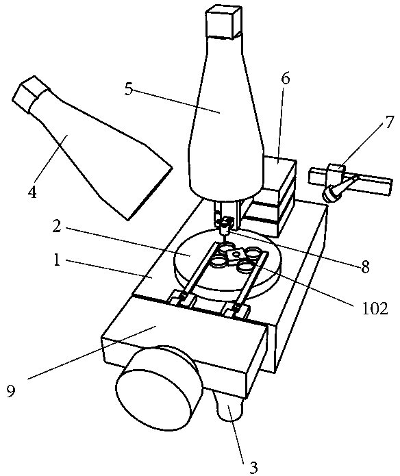
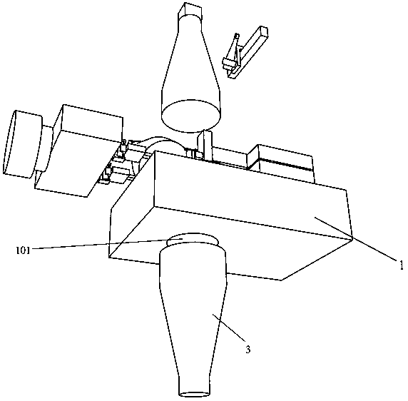
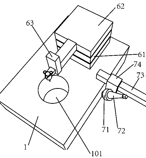
[0043] like Figure 1-8 As shown, a machine vision and scanning detection device includes a detection platform 1, and a perspective hole 101 is provided up and down on the detection platform. The upper surface of the detection table is fixed with a transparent platform 2, and a second camera 5 is erected directly above the transparent platform. One side of the second camera forms a certain angle with the second camera and is aligned with the transparent platform to erect the first camera 4. The other side of the second camera forms a certain angle with the second camera and aligns with the transparent platform to set up a structured light scanning mechanism 7, and the front side of the detection table is provided with a movable fixture 9, which extends to the t...


PUM


Abstract

The invention relates to a machine vision and scanning detection device and a working method thereof. The detection device comprises a detection table, a perspective hole is formed in the detection table in an up-down penetrating manner, a backlight source is erected below the detection table and is opposite to the perspective hole, a transparent platform is fixedly arranged on the upper surface of the detection table right above the perspective hole, a second camera is erected right above the transparent platform, one side of the second camera forms a certain included angle with the second camera and aligns to the transparent platform to erect the first camera, the other side of the second camera forms a certain included angle with the second camera and is aligned with the transparent platform to erect a structured light scanning mechanism, a movable clamp is arranged in front of the detection table, the movable clamp extends to the transparent platform to be used for limiting, a triaxial moving platform is installed at the rear side of the detection table, and a measuring head is fixedly arranged on the Z axis of the triaxial detection table. The machine vision and scanning detection device is reasonable in structure, and the problems that a vision or scanning single detection method is narrow in application range, low in scanning detection efficiency and inconvenient in partclamping, positioning, taking and placing for a long time are solved.

Description

technical field [0001] The invention relates to the technical field of part size detection, and relates to a machine vision and scanning detection device and a working method thereof. Background technique [0002] At present, there are many kinds of automatic detection methods for parts, but each detection method has many limitations, so that the detection of a part requires multiple detection processes, which can only be completed by using different detection instruments, as follows: [0003] The detection efficiency of monocular vision and binocular vision is very high, but the material and surface features of the parts themselves (whether smooth, curved, reflective, surface texture, etc.) have a great influence on the accuracy of the detection results. Parts with different materials and surface features It is necessary to use different types of light sources with different structures, and the angles and directions of lighting are also different. The general performance of...

Claims


Application Information

Patent Timeline
IPC IPC(8): G01B11/00G01B11/25
CPCG01B11/002G01B11/2504G01B11/2545
Inventor 涂宝章黄友杰
Owner 三明图灵智能科技有限公司
Learn More