An underwater uniform pressure exhaust launch experiment device
An experimental device and launch tube technology, applied in the field of underwater testing, can solve the problems of difficult air cavity, insufficient pressure in the cavity, complicated operation, etc., and achieve the effect of expanding the filling space, stable posture, and large internal space
- Summary
- Abstract
- Description
- Claims
- Application Information
AI Technical Summary
Problems solved by technology
Method used
Image
Examples
specific Embodiment approach 1
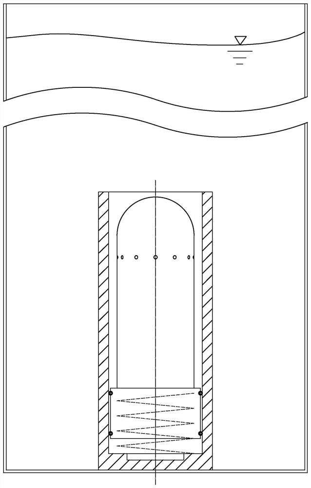
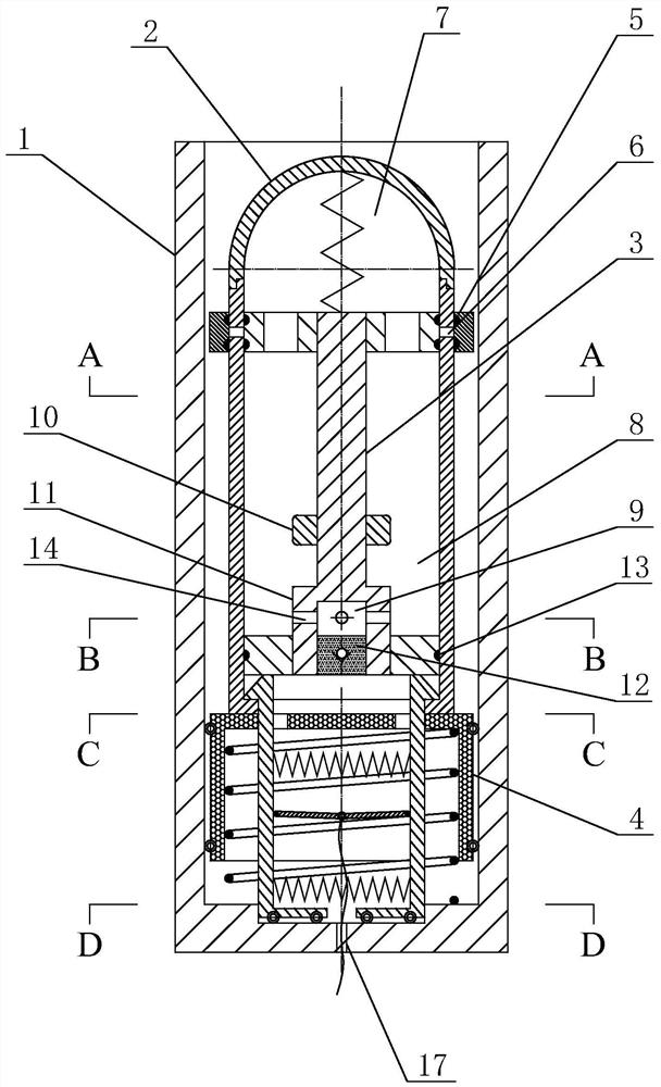
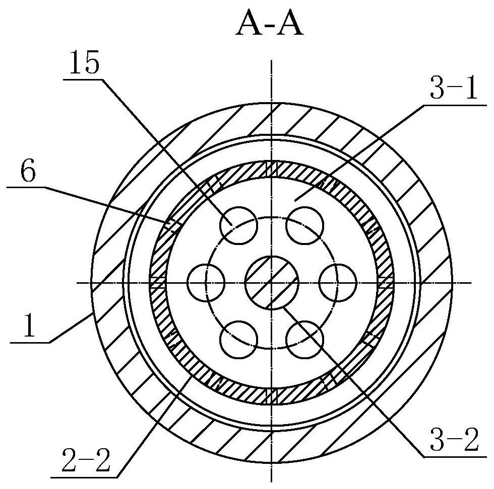
[0037] Specific implementation mode one: combine figure 1 , figure 2 , image 3 , Figure 4 , Figure 5 , Figure 6 , Figure 7 , Figure 8 , Figure 9 and Figure 10Describe this embodiment. This embodiment includes a launch tube 1, a navigation body 2, a double-headed piston 3, a pusher 4 and a sealing ring 5, and the navigation body 2 and the pusher 4 are sequentially arranged in the launch tube 1 from top to bottom. , the navigation body 2 makes the action of ejecting the launch tube 1 under the push of the pusher 4, the navigation body 2 includes a head cover 2-1 and a column body 2-2, and the head cover 2-1 is detachably connected to the body of the column body 2-2. The top, the top of the column body 2-2 is processed with an exhaust hole 6 along its circumferential direction, the bottom of the column body 2-2 is provided with a first bottom hole 2-3, and the double-headed piston 3 is vertically arranged on the column body 2-2. Inside, the upper end of the doub...
specific Embodiment approach 2
[0042] Embodiment 2: This embodiment is a further limitation of Embodiment 1. The double-headed piston 3 includes an upper plug head 3-1, a plug rod 3-2 and a lower plug head 3-3. The upper plug head 3-1, the plug The rod 3-2 and the lower plug head 3-3 are sequentially arranged in the navigation body 2 from top to bottom, and the two ends of the plug rod 3-2 are respectively fixedly connected with the upper plug head 3-1 and the lower plug head 3-3, and the head The cover 2-1 and the upper plug head 3-1 enclose to form the main air chamber 7, and the upper plug head 3-1, the lower plug head 3-3 and the inner wall of the column body 2-2 enclose to form the secondary air chamber 8. The main air chamber 7 communicates with the auxiliary air chamber 8 .
specific Embodiment approach 3
[0043] Specific embodiment three: this embodiment is a further limitation of specific embodiment two, the lower end of the plug rod 3-2 is provided with a connector 11, the connector 11 is fixedly fitted with a lower plug 3-3, and the connector 11 is processed with a The cavity 9 is processed with a first air hole 14 communicating with the auxiliary air cavity 8 on the side wall of the cavity 9 , and the bottom of the connector 11 is provided with a one-way valve 12 communicating with the cavity.
[0044] Further, the shapes of the upper plug head 3-1 and the lower plug head 3-3 are disc-shaped, and the upper plug head 3-1 is processed with a plurality of second vent holes 15 along its circumferential direction, and the main air cavity 7 passes through multiple air holes. A second vent hole 15 communicates with the secondary air chamber 8. The connecting head 11 is processed with a plurality of first air holes 14 along its circumferential direction, and the auxiliary air cavit...
PUM
 Abstract
Description
Claims
Application Information
 - R&D Engineer
- R&D Manager
- IP Professional
- Industry Leading Data Capabilities
- Powerful AI technology
- Patent DNA Extraction
Browse by: Latest US Patents, China's latest patents, Technical Efficacy Thesaurus, Application Domain, Technology Topic, Popular Technical Reports.
© 2024 PatSnap. All rights reserved.Legal|Privacy policy|Modern Slavery Act Transparency Statement|Sitemap|About US| Contact US: help@patsnap.com


