Tool clamp

A tooling and fixture technology, applied in the field of tooling and fixtures, can solve the problems affecting processing efficiency and processing accuracy, difficult to locate and find benchmarks, and consume large labor costs, so as to improve processing efficiency, reduce overall quality, and facilitate processing operations. Effect

Pending Publication Date: 2020-01-17
CHANGAN UNIV
View PDF0 Cites 0 Cited by
  • Summary
  • Abstract
  • Description
  • Claims
  • Application Information

AI Technical Summary

Problems solved by technology

[0004] The main valve body of a low-temperature top-entry ball valve is composed of an upper flange and left and right flanges. It is difficult to process the holes on the flange and the flow channel holes inside the valve body, and the required processing accuracy is high. However, the top-entry type is currently processed The fixture of the main valve body of the cryogenic ball valve uses simple double V-shaped irons to finish the outer flange clamping of the valve body blank, but uses simple two V-shaped irons to clamp the left and right flanges of the valve body , it is difficult to locate and find the datum during the machining process, and every time a flange hole is machined, it must be re-clamped and re-positioned, which brings a lot of trouble during the machining process, especially in modern precision machine tools with indexing devices In fact, this kind of fixture does not make good use of the indexing device, which greatly affects the processing efficiency and processing accuracy, which will consume a lot of labor costs in actual processing

Method used


Image

  • Tool clamp
  • Tool clamp
  • Tool clamp

Examples


Embodiment Construction

[0027] The present invention is further described below in conjunction with accompanying drawing:

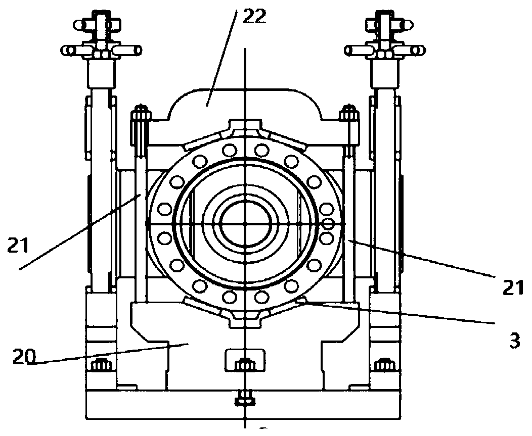
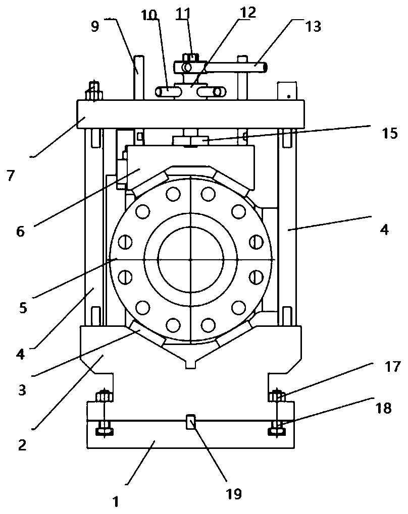
[0028] see Figure 1 to Figure 4 , a tooling fixture, including a fixture base 1, a lower V-shaped positioning seat 2, a threaded column 4, an upper V-shaped positioning seat 6, a beam 7, a middle lower V-shaped positioning seat 20, a middle positioning column 21, and a middle upper V-shaped positioning Seat 22 and locking device; two lower V-shaped positioning seats 2 are symmetrically arranged on the fixture base 1, and each lower V-shaped positioning seat 2 is symmetrically and vertically provided with two threaded columns 4, and the two threaded columns on the same side 4 is set with a crossbeam 7, the lower surface of the crossbeam 7 is provided with an upper V-shaped positioning seat 6 through a locking device, and the locking device is set through the crossbeam 7; the clamp base 1 between the two lower V-shaped positioning seats 2 The top is provided with a middle lower ...


PUM


Abstract

The invention relates to a tool clamp. The tool clamp comprises a clamp base, lower V-shaped positioning bases, threaded columns, upper V-shaped positioning bases, beams, a middle lower V-shaped positioning base, middle positioning columns, middle upper V-shaped positioning bases and locking devices; the two lower V-shaped positioning bases are symmetrically arranged on the clamp base, each lowerV-shaped positioning base is symmetrically and vertically provided with the two threaded columns, each beam sleeves the portion between the two threaded columns of the same side, the upper V-shaped positioning bases are arranged on the lower surfaces of the beams through the locking devices, and the locking devices penetrate through the beams; the portion, between the two lower V-shaped positioning bases, on the clamp base is provided with the middle lower V-shaped positioning base, the middle lower V-shaped positioning base is symmetrically and vertically provided with the two middle positioning columns, and the tops of the two middle positioning columns are provided with the middle upper V-shaped positioning bases. The processing efficiency is improved, the overall weight of a tool is low, a valve is conveniently assembled, clamped and disassembled, and the labor output of processing workers and manual cost are greatly reduced.

Description

technical field [0001] The invention belongs to the technical field of fixtures and fixtures, in particular to a fixture for fixtures. Background technique [0002] In today's digital production, reasonable processing and product measurement are of great help to improve processing accuracy. The internal structure of the main valve body of the cryogenic ball valve is complex, and the requirements for the tightness of the valve body and the coaxiality of the valve body hole are relatively high, which brings great difficulty to the actual processing. To complete a process, its accuracy must be guaranteed, and the processing process must be observed and measured in time. The current machining process is basically completed on automatic lathes and boring machines, so the improvement of machining accuracy requires two guarantees. On the one hand, processing personnel are required to have good processing experience and skilled processing skills; on the other hand, it is also an i...

Claims


Application Information

Patent Timeline
Patent Type & Authority Applications(China)
IPC IPC(8): B23Q3/06B23Q3/10
CPCB23Q3/062B23Q3/104
Inventor 赵悟王东恒杨泽文秦新文赵文军姜文涛杨静邵昉亮
Owner CHANGAN UNIV
Why Eureka
Try Eureka