
Automatic feeding equipment for livestock cultivation

A technology for automated feeding and equipment, applied in animal feeding devices, applications, animal husbandry, etc., can solve problems such as reduced economic benefits, increased breeding costs, and high work intensity, to improve uniformity, avoid economic losses, and avoid Running incoherent effects

Pending Publication Date: 2020-01-17
江门健维自动化设备有限公司
View PDF0 Cites 11 Cited by
  • Summary
  • Abstract
  • Description
  • Claims
  • Application Information

AI Technical Summary

Problems solved by technology

[0002] Livestock is a highly domesticated animal and a social product of long-term human labor. It has unique economic characteristics and can meet human needs. It has formed different varieties. Under the conditions of artificial breeding, it can reproduce normally and can be artificially selected. and the change of production direction, at the same time, its traits can be inherited stably. With the development of modernization, the raising of livestock has changed from family raising to industrialized raising to meet the needs of urbanization, but industrialized raising is generally Large batches, so if artificial feeding is used, the work intensity will be very high, which is not conducive to the breeding, so people start to use mechanical feeding, but the mechanical feeding also needs workers to start it regularly, once forgotten, it will cause the feed to be put in. Make livestock starve, increase breeding cost, and reduce economic benefits. Therefore, an automatic feeding equipment for livestock breeding is proposed

Method used


Image

  • Automatic feeding equipment for livestock cultivation
  • Automatic feeding equipment for livestock cultivation
  • Automatic feeding equipment for livestock cultivation

Examples


Embodiment Construction

[0021] The following will clearly and completely describe the technical solutions in the embodiments of the present invention with reference to the accompanying drawings in the embodiments of the present invention. Obviously, the described embodiments are only some, not all, embodiments of the present invention. Based on the embodiments of the present invention, all other embodiments obtained by persons of ordinary skill in the art without making creative efforts belong to the protection scope of the present invention.

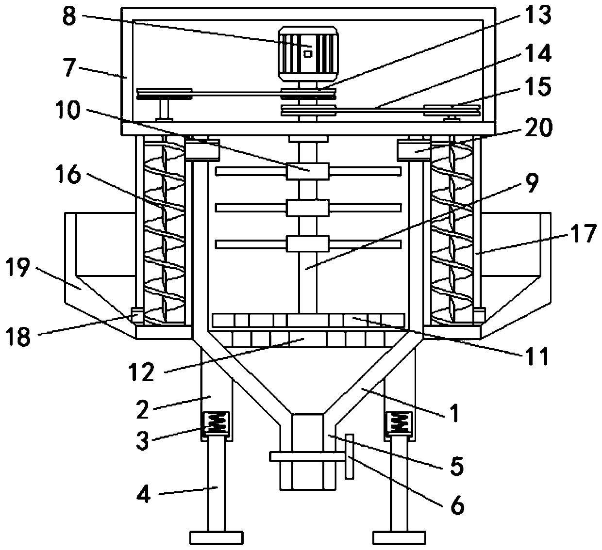
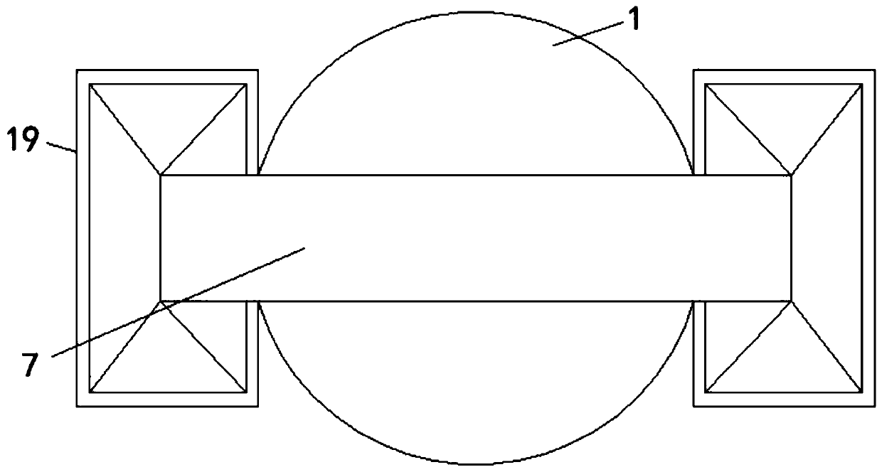
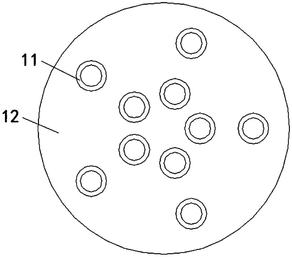
[0022] see Figure 1-3 , an automatic feeding device for livestock breeding, comprising a device main body 1, a support sleeve rod 2 is fixedly installed on the side of the bottom end of the device main body 1, a buffer spring 3 is fixedly installed in the inner cavity at the bottom of the support sleeve rod 2, and a buffer spring 3 is fixedly installed at the bottom of the buffer spring 3 The end is fixedly installed on the top of the support leg 4, the numbe...


PUM


Abstract

The invention relates to the technical field of automatic equipment, and discloses automatic feeding equipment for livestock cultivation. The equipment comprises an equipment main body, wherein supporting sleeve rods are fixedly mounted on the side surface of the bottom end of the equipment main body; buffer springs are fixedly mounted in inner cavities at the bottom of the supporting sleeve rods;the bottom ends of the buffer springs are fixedly mounted at the top ends of supporting legs; the middle of the bottom end of the equipment main body fixedly sleeves a feeding port; and the feeding port fixedly sleeves a valve. According to the equipment, a blanking plate is arranged at the bottom of the inner cavity of the equipment main body, small holes are formed in the blanking plate, corresponding small holes are further formed in a rotating plate, and a rotating shaft fixedly sleeves the rotating plate, so that when a rotating motor is connected with a power supply to drive the rotating shaft to rotate, the rotating plate is driven to rotate together, and when the small holes on the rotating plate rotate to coincide with the small holes on the blanking plate, feeds on the rotatingplate fall into the feeding port and is discharged, so that the automatic feeding function is realized.

Description

technical field [0001] The invention relates to the technical field of automation equipment, in particular to an automatic feeding equipment for livestock breeding. Background technique [0002] Livestock is a highly domesticated animal and a social product of long-term human labor. It has unique economic characteristics and can meet human needs. It has formed different varieties. Under the conditions of artificial breeding, it can reproduce normally and can be artificially selected. and the change of production direction, at the same time, its traits can be inherited stably. With the development of modernization, the raising of livestock has changed from family raising to industrialized raising to meet the needs of urbanization, but industrialized raising is generally Large batches, so if artificial feeding is used, the work intensity will be very high, which is not conducive to the breeding, so people start to use mechanical feeding, but the mechanical feeding also needs w...

Claims


Application Information

Patent Timeline
IPC IPC(8): A01K5/02B01F15/02B01F7/18
CPCA01K5/02A01K5/0225A01K5/0241B01F27/90B01F35/71775B01F35/7547B01F2101/18
Inventor 卢育兵
Owner 江门健维自动化设备有限公司
Learn More