Transformer structure with effects of bearing large current and dissipating heat

A technology of transformers and radiators, applied in the direction of transformers, fixed transformers, electrical component structure associations, etc., can solve problems such as unsatisfactory, unable to withstand large currents and heat dissipation effects, and achieve enhanced overall current resistance, heat dissipation, The effect of large cooling area

Inactive Publication Date: 2020-01-14
徐州国力电力设备有限公司
View PDF0 Cites 0 Cited by
  • Summary
  • Abstract
  • Description
  • Claims
  • Application Information

AI Technical Summary

Problems solved by technology

[0005] The main purpose of the present invention is to solve the problem that the conventional structure cannot withstand large current and the heat dissipation effect is not satisfactory

Method used


Image

  • Transformer structure with effects of bearing large current and dissipating heat
  • Transformer structure with effects of bearing large current and dissipating heat
  • Transformer structure with effects of bearing large current and dissipating heat

Examples


Embodiment Construction

[0020] The following will clearly and completely describe the technical solutions in the embodiments of the present invention with reference to the accompanying drawings in the embodiments of the present invention. Obviously, the described embodiments are only some, not all, embodiments of the present invention.

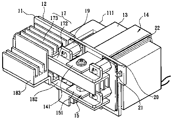
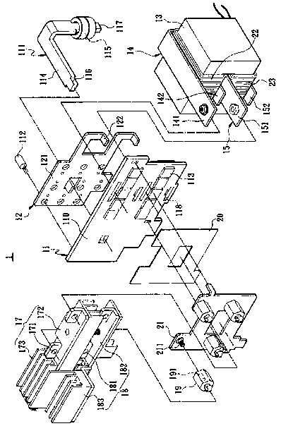
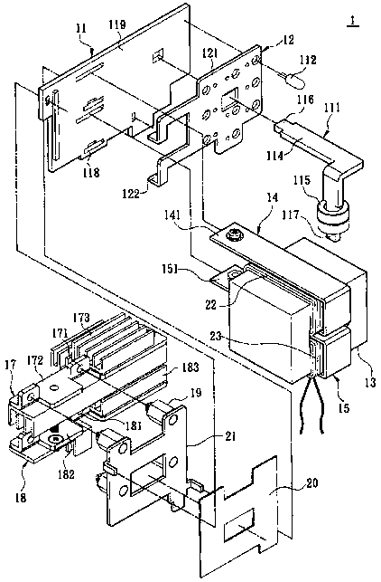
[0021] see Figure 1-4 , the present invention provides a transformer structure 1 . The transformer structure 1 is constructed in one piece to increase the power density of the transformer structure 1 . The transformer structure 1 comprises a circuit board 11 , a current carrying board 12 , a transformer core 13 , two board windings 14 , 15 and two wire windings 22 , 23 . The circuit board 11 is a printed circuit board (PCB), and includes wires (not shown) thereon. In addition, the circuit board 11 is provided with a rectification filter circuit, which at least includes a filter inductor 111 , a filter capacitor 112 and a rectification switch 113 . The filter indu...


PUM


Abstract

The invention discloses a transformer structure with effects of bearing large current and dissipating heat. The transformer structure includes a circuit board, a current bearing plate, a transformer core, two wire windings and two plate windings. A rectifying and filtering circuit is disposed on the circuit board and includes at least a filtering inductor, a filtering capacitor and a rectifying switch. The filtering inductor is composed of a deflector on the circuit board and an inductor core placed on the deflector. The current bearing plate is stacked on the circuit board and is electricallyconnected to the rectifying and filtering circuit. The transformer core is disposed on the circuit board. The two plate windings are made of electrode plate materials. At least one round of iron coreis wound around the transformer and fixed on the circuit board. The plate windings are electrically connected to the deflector and the current bearing plate to jointly bear the current flowing through the transformer structure.

Description

technical field [0001] TECHNICAL FIELD The present invention relates to a transformer structure, in particular to a transformer structure with high power density, capable of withstanding large current and effectively dissipating heat. Background technique [0002] There are many transformer structures pursuing higher power density and realizing it through integrated structures. [0003] However, the above-mentioned patents only focus on higher power density without considering the current-carrying capacity of the transformer structure, so these patents cannot be effectively applied to common high-power working conditions. [0004] In addition, since the above-mentioned transformer structure does not consider the current bearing capacity of the transformer, the temperature rise is very significant during the implementation of the transformer, resulting in a decrease in transformer efficiency. Also, if an external heat sink is required to dissipate the heat, the intended high...

Claims


Application Information

Patent Timeline
Patent Type & Authority Applications(China)
IPC IPC(8): H01F27/28H01F27/40H01F27/08H01F27/22H01F30/06
CPCH01F27/08H01F27/22H01F27/2847H01F27/2852H01F27/40H01F30/06H01F2027/408
Inventor 张海峰
Owner 徐州国力电力设备有限公司
Why Eureka
Try Eureka