Sample arm light path structure and OCT imaging system

A technology of imaging system and sample arm, which is applied in optics, optical components, color/spectral characteristic measurement, etc., can solve the problems of high cost of OCT imaging system and difficulty in popularizing OCT scanning technology, and achieve the effect of solving high cost

Pending Publication Date: 2020-01-14
SHENZHEN INST OF TERAHERTZ TECH & INNOVATION CO LTD +1
View PDF0 Cites 0 Cited by
  • Summary
  • Abstract
  • Description
  • Claims
  • Application Information

AI Technical Summary

Problems solved by technology

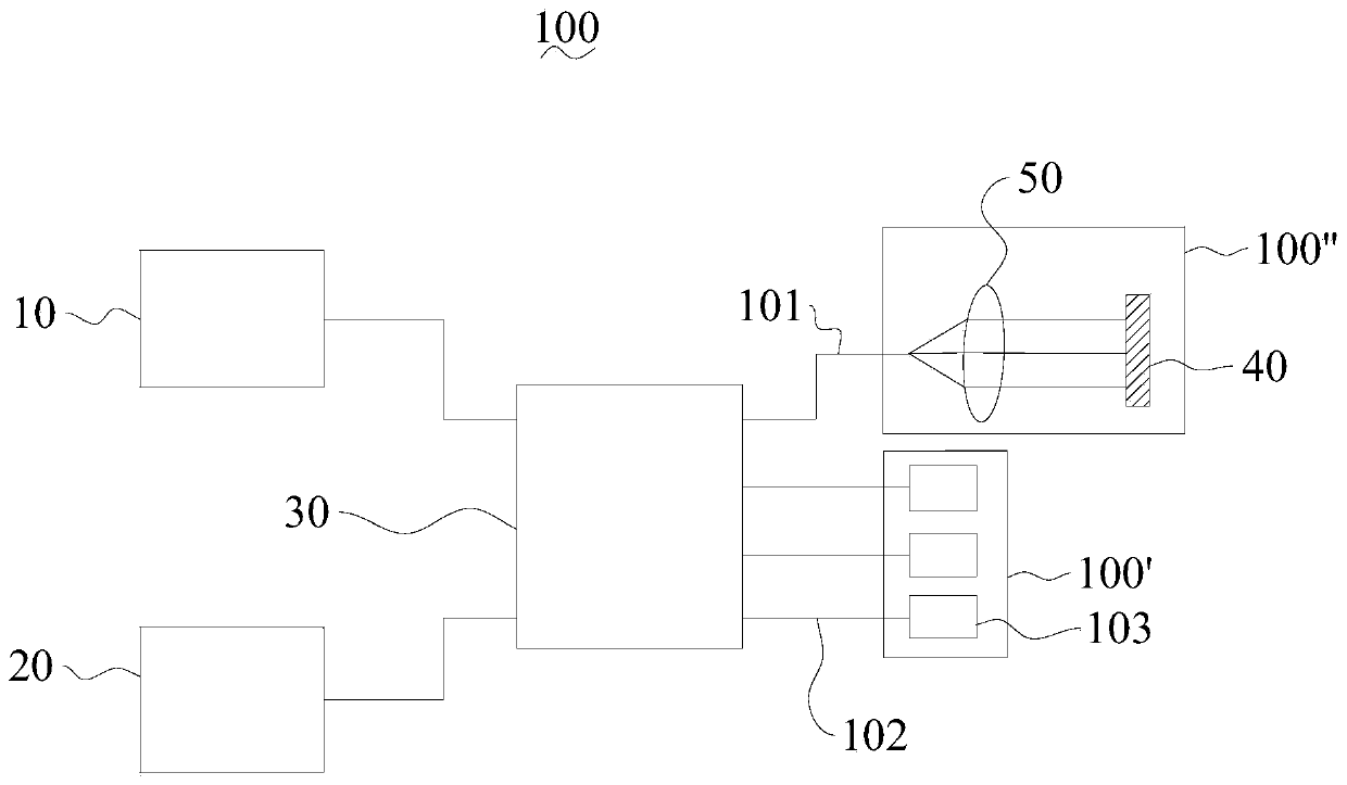
[0006] The purpose of the present invention is to provide a sample arm optical path structure, which aims to solve the problem that the cost of the OCT imaging system is too high and it is difficult to popularize the OCT scanning technology when a plurality of scanning probes are arranged.

Method used


Image

  • Sample arm light path structure and OCT imaging system
  • Sample arm light path structure and OCT imaging system

Examples


Embodiment Construction

[0016] The embodiments of the present invention will be described in detail below. Examples of the embodiments are shown in the accompanying drawings, wherein the same or similar reference numerals indicate the same or similar elements or elements with the same or similar functions. The embodiments described below with reference to the accompanying drawings are exemplary, and are intended to explain the present invention, but should not be construed as limiting the present invention.

[0017] In the description of the present invention, it should be understood that the terms "thickness", "upper", "lower", "vertical", "parallel", "bottom", "angle", etc. indicate the orientation or positional relationship based on the attached The orientation or positional relationship shown in the figure is only for the convenience of describing the present invention and simplifying the description, rather than indicating or implying that the device or element referred to must have a specific orien...


PUM


Abstract

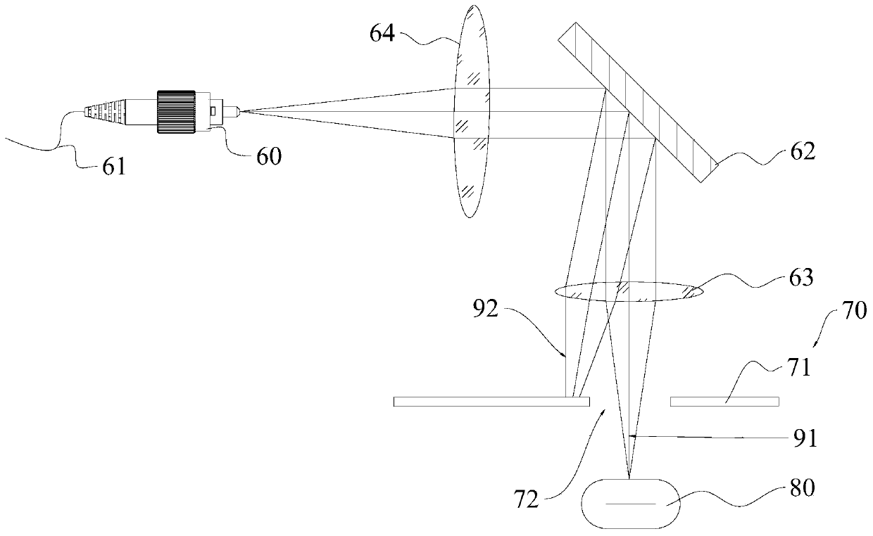
The invention belongs to the technical field of optical coherence tomography, and particularly relates to a sample arm light path structure and an OCT imaging system. The sample arm light path structure comprises sample scanning probes. The sample scanning probe comprises a scanning galvanometer, which is used for incidence of a first light beam, reflects the first light beam to a to-be-detected sample, and receives the first light beam reflected back from the to-be-detected sample; and a light beam control mechanism, which is arranged on the propagation light path of the first light beam andhas a first control state and a second control state. The light beam control mechanism enables the first light beam to be reflected to the to-be-detected sample through the scanning galvanometer underthe first control state, and limits the first light beam to be reflected to the to-be-detected sample through the scanning galvanometer under the second control state. There are multiple sample scanning probes, and at most one light beam control mechanism is in the first control state; and the plurality of scanning probes share one set of broadband light source and one set of spectrum analyzer, so that the problem that the cost is too high because the plurality of scanning probes are arranged in a time division multiplexing occasion is solved.

Description

Technical field [0001] The invention belongs to the technical field of optical coherence tomography, and particularly relates to a sample arm optical path structure and an OCT imaging system. Background technique [0002] Capsules are common medicines in medicine. For a capsule with a liquid sealed inside, if the sealing is poor, the capsule will fail due to liquid leakage; while a capsule with a solid inside, the internal medicine may be oxidized and fail due to poor sealing, so the sealing of the capsule It directly affects the shelf life of the capsule. [0003] At present, in the field of medical preparation, OCT, as a non-destructive testing technology, can detect the fault condition inside the capsule and realize the detection of the capsule's tightness. On the one hand, this kind of detection finds poorly sealed capsules and removes them, improving the yield of capsule preparation; on the other hand, it can monitor the production status of the preparation equipment. [0004...

Claims


Application Information

Patent Timeline
IPC IPC(8): G01N21/25G02B26/10G02B26/08
CPCG01N21/255G02B26/0816G02B26/10
Inventor 苏胜飞
Owner SHENZHEN INST OF TERAHERTZ TECH & INNOVATION CO LTD
Why Eureka
Try Eureka