
An automatic nail insertion device for prefabricated laminated panels with self-contained positioning nails

A technology of positioning nails and laminated plates, which is applied in nailing tools, supply devices, nailing tools, etc., can solve the problems of affecting the installation of heating pipes, difficulty in drilling holes, and falling off, and achieves a fast and automated nailing method. High, increase the effect of the contact area

Active Publication Date: 2021-02-09
ZHEJIANG FAEN INTEGRATED HOUSING CO LTD
View PDF10 Cites 0 Cited by
  • Summary
  • Abstract
  • Description
  • Claims
  • Application Information

AI Technical Summary

Problems solved by technology

[0008] The purpose of the present invention is to address the deficiencies of the prior art. By setting the nailing mechanism, the mud collection assembly uses the sharp drilling part to drill holes when it is closed, and then the insertion assembly automatically enters the hole, and then passes through the mud collection assembly. The opening of the components enables the excavated cement to flow back quickly and automatically under the guidance of the pressure-limiting components, thus solving the problem of large-grained stones encountered when drilling holes on the prefabricated slab after solidification, making it difficult to drill holes, and the nails are installed vertically After that, it may cause falling off, which will affect the technical problems of heating pipe installation, so as to achieve the effect of convenient use and firm installation

Method used


Image

  • An automatic nail insertion device for prefabricated laminated panels with self-contained positioning nails
  • An automatic nail insertion device for prefabricated laminated panels with self-contained positioning nails
  • An automatic nail insertion device for prefabricated laminated panels with self-contained positioning nails

Examples


Embodiment 1

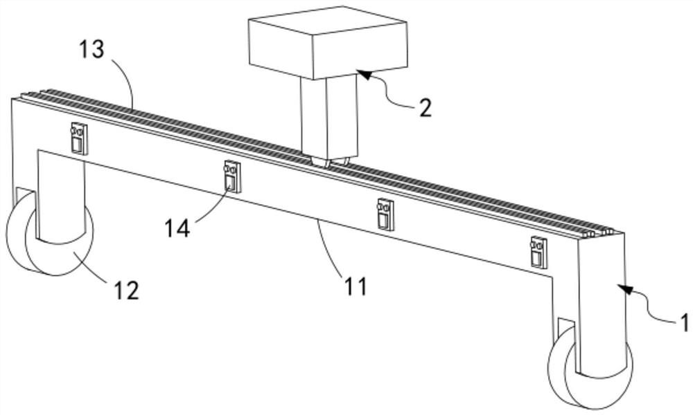
[0069] Such as figure 1 Shown, a kind of plug-in nail 10 retainer, comprising:

[0070] A transverse sliding mechanism 1, which straddles above the prefabricated slab and slides back and forth along the length direction of the prefabricated slab is arranged on the prefabricated slab;

[0071] A longitudinal sliding mechanism 2, the longitudinal sliding mechanism 2 is slidably arranged on the horizontal sliding mechanism 1 along the length direction of the horizontal sliding mechanism 1;

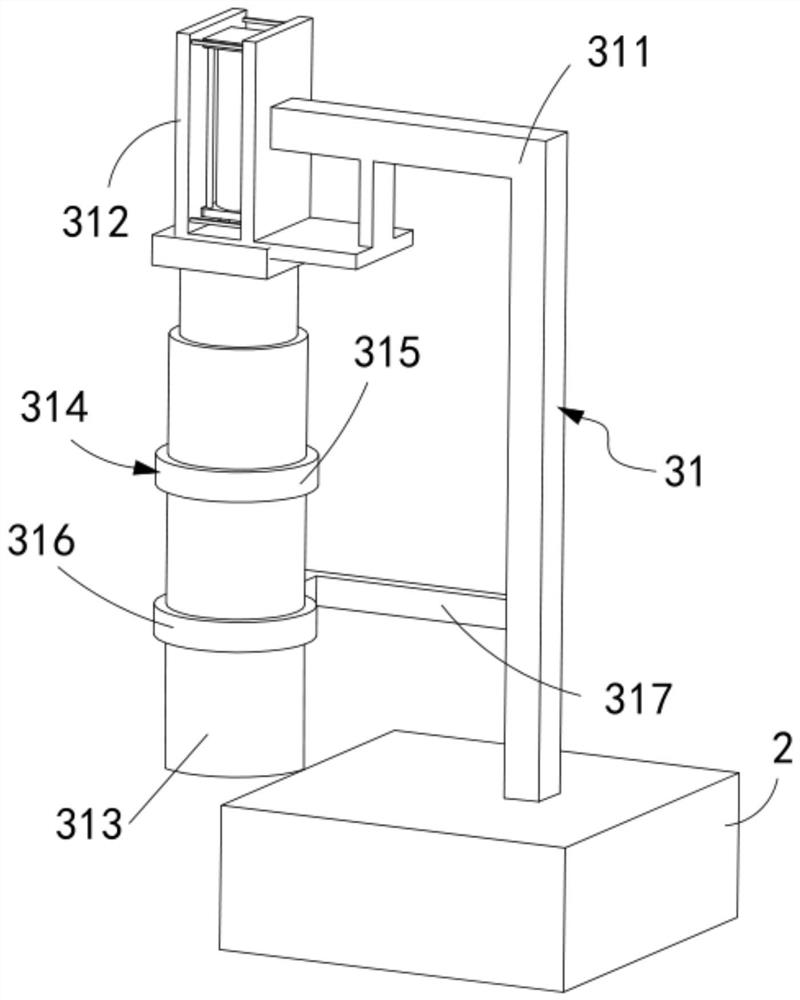
[0072] Nail-introducing mechanism 3, said nail-introducing mechanism 3 includes an insertion assembly 31 arranged on said longitudinal sliding mechanism 2, used for digging holes on the prefabricated board in the closed state and dispersing the cement in the open state into the pits The mud collection assembly 32, the pressure limiting assembly 33 which is sleeved on the insertion assembly 31 and used to limit the cement breaking, and the mud collection assembly 32 is set in conjunction with...

Embodiment 2

[0114] Such as Figure 10 , Figure 11 As shown, the components that are the same as or corresponding to those in the first embodiment are marked with the corresponding reference numerals in the first embodiment. For the sake of simplicity, only the differences from the first embodiment will be described below. The difference between this embodiment two and embodiment one is:

[0115] further, such as Figure 10 , Figure 11 As shown, the control assembly 34 includes:

[0116] Positioning rod 341, the positioning rod 341 is fixedly connected with the pull rod b329 and it is arranged in an L-shaped structure, the positioning rod 341 is provided with several groups corresponding to the pull rod b329; and

[0117] Feed groove 342, described feed groove 342 is opened in described gun barrel 313 and its length direction is vertically set with described gun barrel 313 length direction, and described positioning rod 341 is slidably arranged in described feed groove 342 and Sever...


PUM


Abstract

The invention relates to an automatic nail insertion device for prefabricated laminated panels with positioning nails, comprising: a horizontal sliding mechanism; a longitudinal sliding mechanism; A mud collection assembly for sinking the cement that has been excavated on the cement board and dissipated in the open state into the excavation pit, a pressure limiting assembly and a mud collection assembly that is sleeved on the insertion assembly and used to limit the disintegration of cement A control component that is set in linkage and is used to control the intermittent discharge of nails in the insertion component; The tensioning assembly for paving work and the guiding assembly for guiding the sliding track of the tensioning assembly; the invention solves the problem of large-grained stones encountered when drilling holes on the prefabricated slab after solidification, making it difficult to dig a hole, and the nails are vertical After installation, it may cause falling off, which will affect the technical problems of heating pipe installation.

Description

technical field [0001] The invention relates to the technical field of laying nails on prefabricated panels, in particular to an automatic nail insertion device for prefabricated laminated panels with positioning nails. Background technique [0002] In the heat preservation facilities generally adopted in the prior art, the heating pipes are nailed to the prefabricated board along the track, and the binding method is usually nails on the solidified prefabricated board, and then the iron wire wraps the hose and the nails together to realize Fixing of heating pipes. [0003] Patent No. CN2010202593738 discloses a device for nailing conveniently. It is characterized in that: the nailing device includes upper and lower nail clamping seats, and the upper and lower nail clamping seats are respectively composed of an outer box and a shockproof pad. The mat is fixed and embedded in the outer box, and its mating surface is flush with the bottom surface of the upper and lower nail se...

Claims


Application Information

Patent Timeline
Patent Type & Authority Patents(China)
IPC IPC(8): B27F7/02B28B23/00B28B11/12B28B13/02B28B17/00
CPCB28B11/12B28B13/0225B28B13/0295B28B17/00B28B17/0036B28B23/0062
Inventor 刘永生郑群李云
Owner ZHEJIANG FAEN INTEGRATED HOUSING CO LTD
Learn More