Rubber tapping machine

A technology of rubber tapping machine and rubber tapping, which is applied in forestry, application, agriculture and other directions, can solve the problems of limit column breakage, damage, detachment of tool holder assembly, etc.

Pending Publication Date: 2020-01-10
林焕
View PDF2 Cites 1 Cited by
  • Summary
  • Abstract
  • Description
  • Claims
  • Application Information

AI Technical Summary

Problems solved by technology

The problem is that the tool post assembly and the soft guide rail are only connected by four limit posts. When the tool post assembly moves, the stop post and the soft guide rail will wear each other. After a period of use, the limit The column will be broken due to excessive wear, causing the tool holder assembly to break away from the soft guide rail; the track wheel adopts the transmission mode of gears, and the gears are exposed to the external environment. The gap between the gears is easy to cause the rubber tapping machine to stop due to small stones stuck work, serious and even cause their own damage
The existing problem is that when the rubber tapping machine returns to the initial position after tapping once, the blade of the cutting knife is still located on the already cut rubber flow channel, and the moving cutting knife will hinder the flow of rubber liquid, making the rubber liquid It overflows from the glue flow channel and cannot flow into the carrying container normally, which is easy to cause waste; the lead screw moves the first slider downward through its own rotation, but when the first slider moves downward, the second slider cannot be guaranteed. The slider also moves down the same distance as the first slider, which can easily cause the thickness of the rubber tree to be different every time. Excessive cutting will damage the rubber tree itself and reduce the life of the rubber tree

Method used


Image

  • Rubber tapping machine
  • Rubber tapping machine
  • Rubber tapping machine

Examples


Embodiment 1

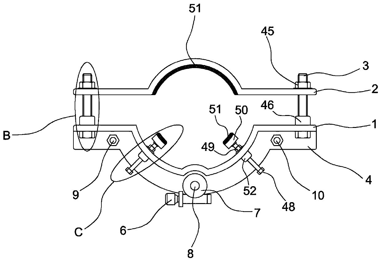
[0022] Example 1, such as figure 1 , Figure 4 , Figure 5 , Figure 6 , Figure 7 , Figure 8 and Figure 9As shown, a rubber tapping machine includes a first arc-shaped frame 1 and a second arc-shaped frame 2, and a first arc-shaped frame is arranged between the first arc-shaped frame 1 and the second arc-shaped frame 2 to connect the two together. The bolt 3 is clamped between the first arc-shaped frame 1 and the second arc-shaped frame 2, the first arc-shaped frame 1 is provided with an upper fixing segment 4, and the first arc-shaped frame 1 is provided with a lower fixing segment 5, The worm gear screw lifter 7 with the first motor 6 is arranged on the upper surface of the upper fixed section 4, and the worm gear screw lifter 7 is provided with a screw 8, and the first sliding rod 9 and the second sliding rod 10 are respectively fixed on the upper fixing segment 4 and the lower fixed section 5, the first sliding rod 9 is provided with a short sleeve 11, the second ...

Embodiment 2

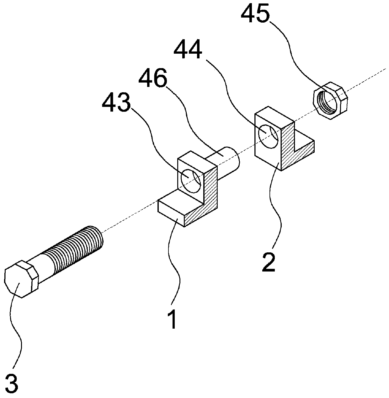
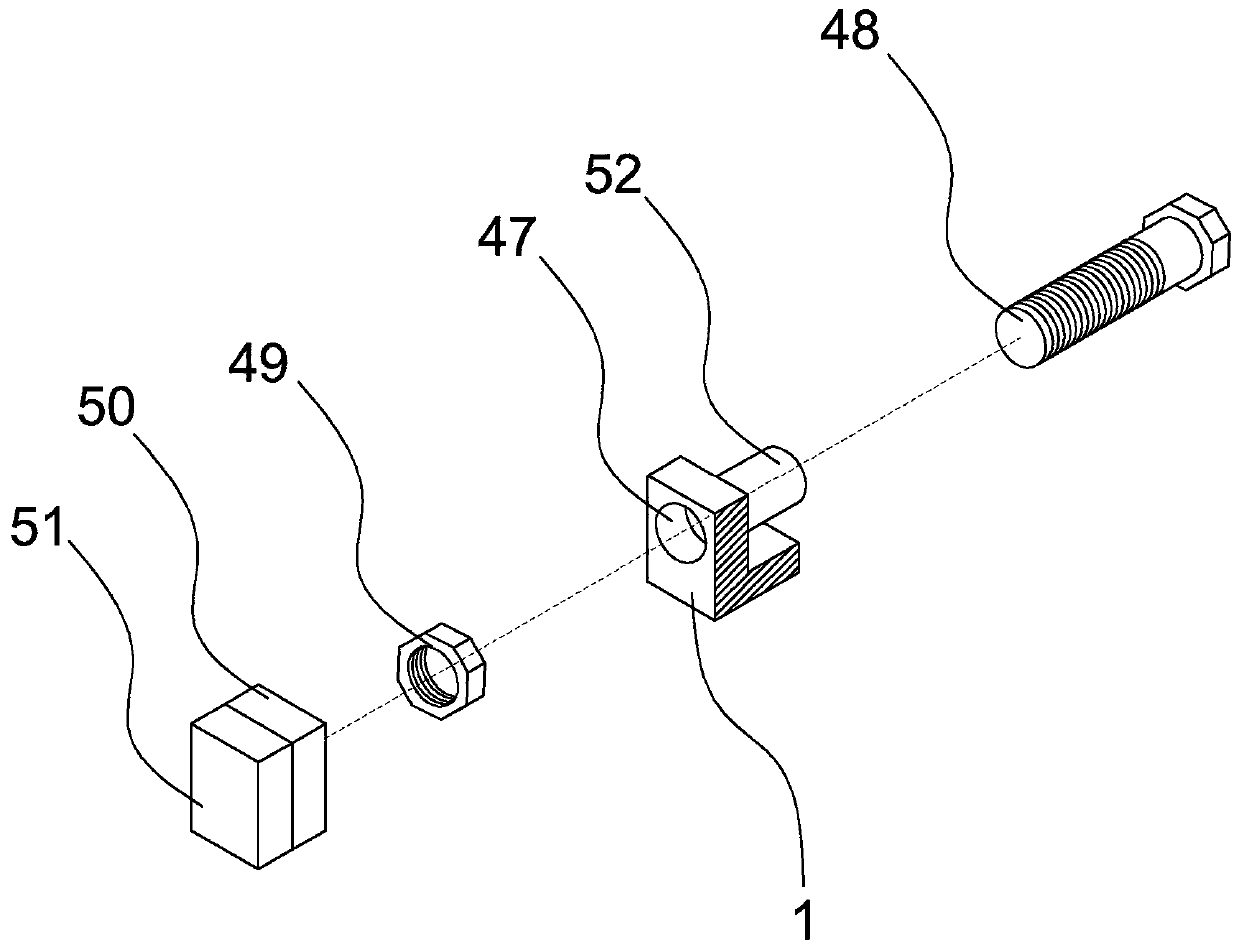
[0029] Example 2, such as figure 1 and image 3 As shown, the first arc-shaped frame 1 is provided with a fourth fixing hole 47, the fourth fixing hole 47 is provided with a second bolt 48, the inner surface of the first arc-shaped frame 1 is provided with a second nut 49, and the second nut 49 is connected to the second bolt 48, the fixing plate 50 is arranged at one end of the second bolt 48, and the fixing plate 50 and the second arc frame 2 are in a clamping state. Because rubber trees have different growth degrees and have different cross-sectional diameters, this rubber tapping machine can adjust the distance between the fixing plate 50 and the second arc frame 2 by rotating the second bolt 48 to adapt to rubber trees of different sizes. Ensure that the fixed plate 50 and the second arc-shaped frame 2 can clamp the trunk of the rubber tree mutually. After the distance between the fixed plate 50 and the second arc-shaped frame 2 has adapted to the cross-sectional diamete...


PUM


Abstract

The invention relates to the technical field of mechanical tapping of natural rubber, in particular to a rubber tapping machine. The rubber tapping machine comprises a first arc frame and a second arcframe, and the first arc frame and the second arc frame are in a clamping state and connected through first bolts arranged between the first arc frame and the second arc frame. The first arc frame isprovided with an upper fixing fragment and a lower fixing fragment, and a worm gear screw lift with a first motor is arranged on the upper surface of the upper fixing fragment and provided with a screw rod internally. A first slide rod and a second slide rod are fixed between the upper fixing fragment and the lower fixing fragment, the first slide rod is provided with a short sleeve, the second slide rod is provided with a long sleeve, and an arc plate is arranged between the short sleeve and the long sleeve and enables connection of the short sleeve and the long sleeve. The rubber tapping machine has advantages that rubber tapping of rubber trees can be completed automatically, and labor intensity is relieved while production cost is reduced.

Description

technical field [0001] The invention relates to the technical field of mechanical tapping of natural rubber. Background technique [0002] Since humans discovered that rubber trees can produce natural rubber, they have been manually cutting the skin of the rubber tree with a rubber tapping knife to make the rubber tree ooze out the rubber liquid, and then use the rubber flow channel formed by the rubber tree skin to collect the rubber liquid into the liquid collection container. However, rubber tapping is a high-tech job. The level of rubber tapping technology will not only affect the output of rubber liquid, but also affect the production cycle of rubber liquid, and even affect the life of rubber trees. The rubber cutting work needs to be started in the early morning and collected every three hours. Once, the labor intensity is high, the labor efficiency is low, and the production cost is expensive. [0003] In the Chinese patent document whose application number is 201721...

Claims


Application Information

Patent Timeline
Patent Type & Authority Applications(China)
IPC IPC(8): A01G23/12
CPCA01G23/12
Inventor 林焕
Owner 林焕
Why Eureka
Try Eureka