Welding wire reel frame

A welding wire reel and turntable technology, applied in welding equipment, auxiliary welding equipment, welding/cutting auxiliary equipment, etc., can solve the problem of wire sticking, etc., and achieve the effect of smooth wire feeding, no sticking, and flexible rotation.

Inactive Publication Date: 2020-01-07
湖北新冶金属表面处理科技有限公司
View PDF0 Cites 0 Cited by
  • Summary
  • Abstract
  • Description
  • Claims
  • Application Information

AI Technical Summary

Problems solved by technology

[0003] The object of the present invention is to provide a welding wire reel rack to solve the problem of welding wire stuck in the above welding process

Method used


Image

  • Welding wire reel frame
  • Welding wire reel frame
  • Welding wire reel frame

Examples


Embodiment Construction

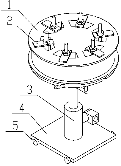
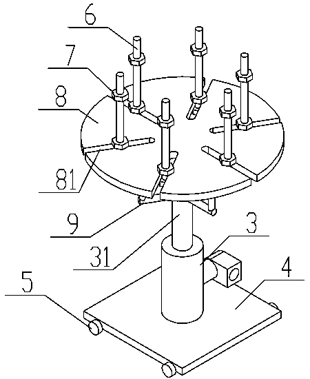
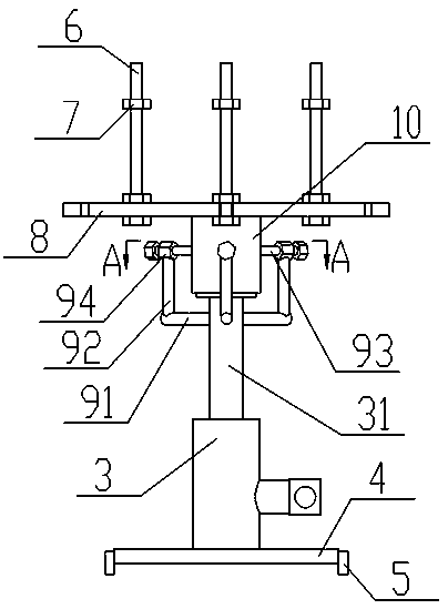
[0017] see Figure 1-5 , present embodiment comprises base 4, and jack 3 is housed on base 4, and the top of piston rod 31 of jack 3 is equipped with sleeve 10 through slewing bearing 11, and the top of sleeve 10 is fixedly connected with a turntable 8, and on turntable 8 radially uniform A plurality of elongated through holes 81 are provided, each elongated through hole 81 is equipped with a support column 6 through a bolt, each support column 6 is set with a pressing plate 2, and a compression nut 7 is installed above the pressing plate 2.

[0018] The bottom of the base 4 in this embodiment is provided with rollers 5 .

[0019] The jack 3 described in this embodiment is a screw jack, and the QL3.2 screw jack produced by Shanghai Qize Hoisting Machinery Co., Ltd. is selected for use.

[0020] The piston rod 31 of the jack 3 described in this embodiment is evenly equipped with at least three brackets 9 (specifically three), and the upper end of the bracket 9 is close to the ...


PUM


Abstract

The invention relates to the technical field of welding, in particular to a welding wire reel frame. The frame comprises a base, wherein a jack is arranged on the base, the top of a piston rod of thejack is provided with a sleeve through a pivotal bearing, a rotary disc is fixedly connected to the top of the sleeve, a plurality of elongated through holes are uniformly formed in the rotary disc inthe radial direction, supporting columns are mounted in the elongated through holes through bolts, and a pressing nut is arranged on each supporting column. The welding wire reel frame is smoother inwire feeding and more flexible to use.

Description

technical field [0001] The invention relates to the field of welding technology, in particular to a welding wire reel frame. Background technique [0002] Steel plate production usually adopts roll rolling, and the roll rolls cylindrical billets or rectangular billets into thin steel plates. As the rolls are used for a long time, the surface of the rolls will be greatly worn. In the end, the production quality cannot be guaranteed, and the cost of replacing the rolls is too high. , in order to save costs, the worn rolls are usually removed for surfacing repair; surfacing is usually automatically welded by an electric welding machine, and welding wire needs to be continuously fed to the welding torch head during the welding process. Near the welding operation site, the welding wire will often drive the welding wire reel to rotate when feeding the welding wire. Sometimes, due to the high friction between the welding wire reel and the ground, the welding wire will get stuck, an...

Claims


Application Information

Patent Timeline
Patent Type & Authority Applications(China)
IPC IPC(8): B23K37/00
CPCB23K37/00
Inventor 盛文胜王克非
Owner 湖北新冶金属表面处理科技有限公司
Why Eureka
Try Eureka