Underwater beacon positioning method of underwater vehicle

A technology of underwater vehicle and positioning method, which is applied to satellite radio beacon positioning systems, instruments, navigation and other directions, and can solve problems such as position deviation and clock drift of underwater beacons at the speed of sound and sound.

Active Publication Date: 2020-01-03
HARBIN ENG UNIV
View PDF5 Cites 1 Cited by
  • Summary
  • Abstract
  • Description
  • Claims
  • Application Information

AI Technical Summary

Problems solved by technology

[0003] The purpose of the present invention is to propose an underwater vehicle based on the expectation maximization method in view of the unknown speed of sound in underwater single beacon positioning, the position deviation of underwater beacons and the clock drift of the underwater acoustic signal transceiver. underwater beacon positioning method

Method used


Image

  • Underwater beacon positioning method of underwater vehicle
  • Underwater beacon positioning method of underwater vehicle
  • Underwater beacon positioning method of underwater vehicle

Examples


Embodiment 1

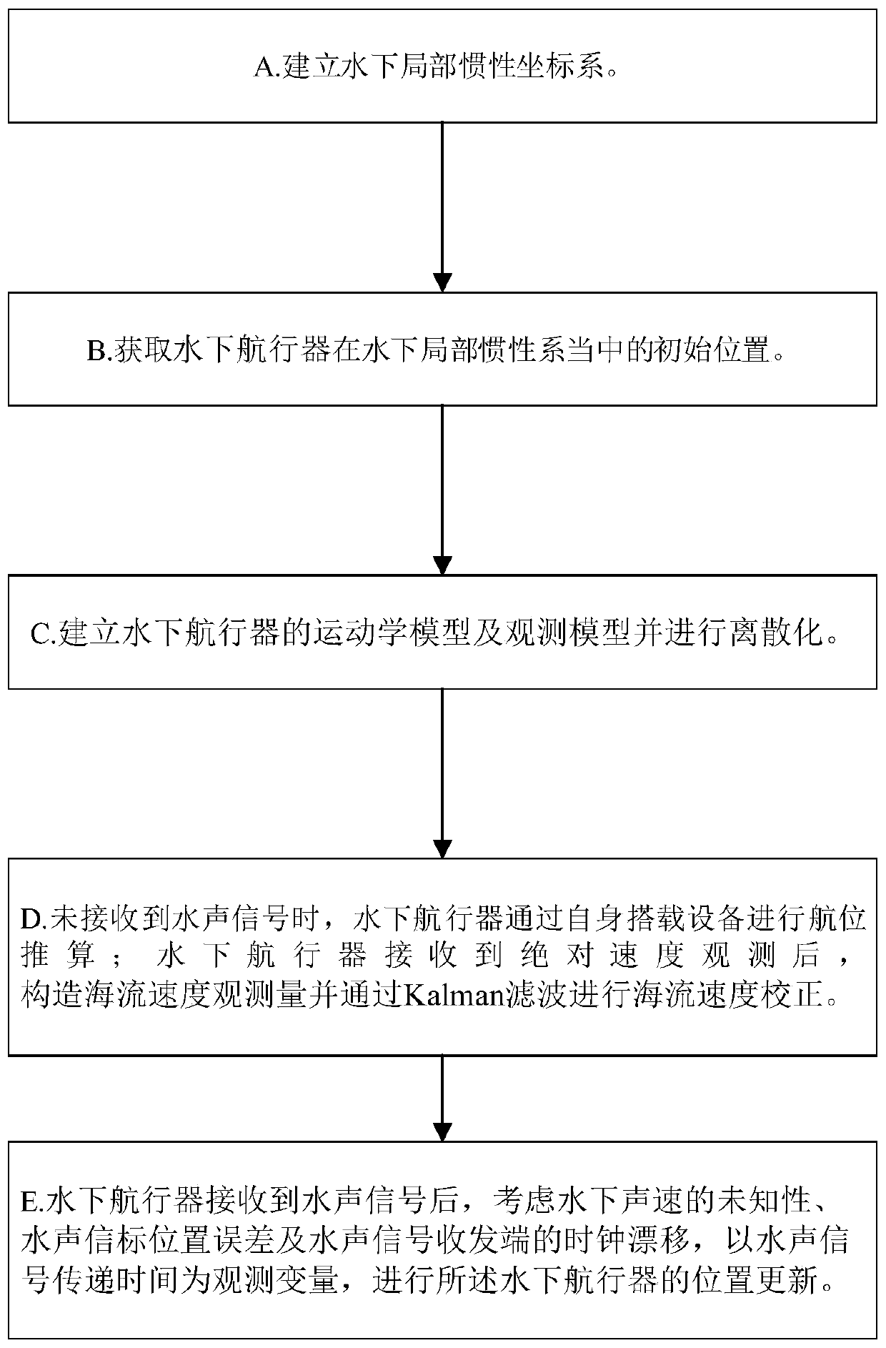
[0121] Embodiment 1, see attached figure 1 A kind of underwater beacon location method of underwater vehicle, comprises the following steps:

[0122] A. Take any point in the positioning area as the origin, set the east, north, and sky directions as x, y, and z axes respectively, and establish an underwater local inertial coordinate system;

[0123] B. Obtain the initial position of the underwater vehicle in the underwater local inertial system through the GPS system carried by the underwater vehicle;

[0124] C. Establish the kinematics model and observation model of the underwater vehicle and perform discretization;

[0125] The establishment method of the kinematic model is as follows:

[0126] Define the state vector as:

[0127] x=[x y v cx v cy ] T

[0128] Among them: x, y are the horizontal position of the underwater vehicle in the underwater local inertial coordinate system; v cx , v cy is the unknown current velocity;

[0129] Deriving x and adding the noi...

Embodiment 2

[0234] Embodiment 2, the algorithm pseudocode of the present invention is summarized as:

[0235]

Embodiment 3

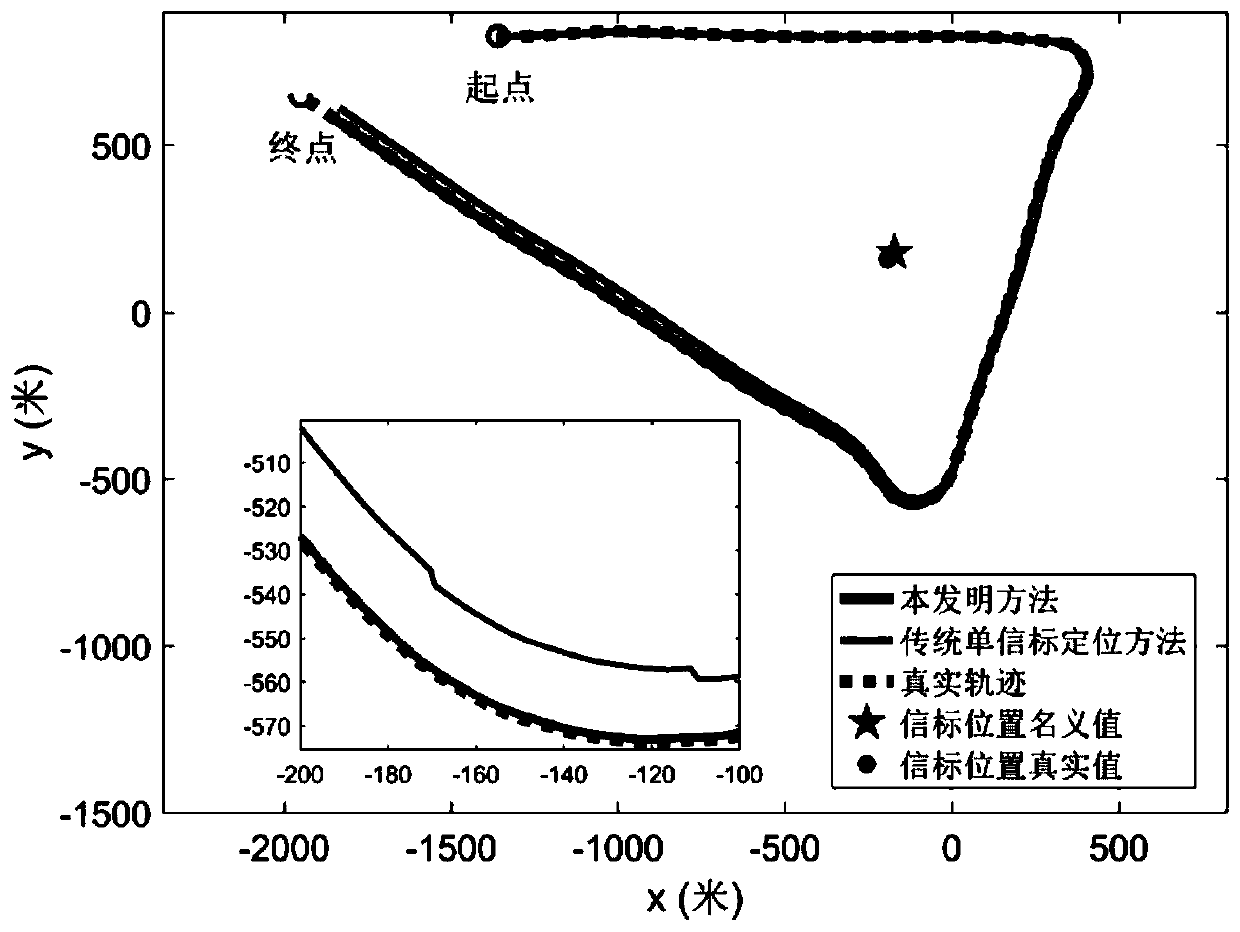
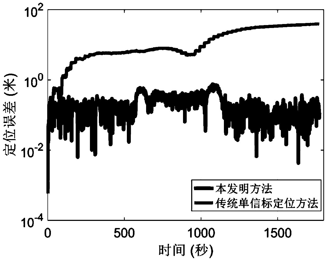
[0236] Example 3, using the method described in Example 1 to verify through experimental data.

[0237]As a comparison, this embodiment also shows the positioning results of the traditional underwater single-beacon positioning method. The method of collecting experimental data is as follows: the surface ship is equipped with GPS, hydrophone and compass, and performs two-dimensional movement on the water surface. The trajectory of the surface ship observed by GPS is used as a real reference, and the hydrophone receives the underwater acoustic signal emitted by the underwater acoustic beacon fixed on the bottom of the water, and obtains the transmission time of the underwater acoustic signal. Since the surface ship is not equipped with a Doppler velocimeter, the GPS track is used to make a difference and the heading angle measured by the electronic compass is used to simulate the ground speed of the aircraft observed by the Doppler velocimeter. In the experiment, the underwater...


PUM


Abstract

The invention belongs to the technical field of underwater positioning, in particular to an underwater beacon positioning method of an underwater vehicle. The method comprises the steps of: an acoustic beacon periodically broadcasts a submarine sound signal; when the underwater vehicle does not receive the submarine sound signal, the underwater vehicle performs dead reckoning through an own electronic compass and a depthometer by reading the rotating speed information of an own propeller, constructs ocean current velocity observation and measurement after receiving an absolute velocity measured by a loaded Doppler tachymeter, and corrects the ocean current velocity through Kalman filtering; and after receiving the submarine sound signal, the underwater vehicle considers unknown property ofthe underwater sound velocity, a position error of the acoustic beacon and a clock drift of an submarine sound signal receiving and sending end, so as to update the position of the underwater vehiclebased on an extended Kalman filtering algorithm and an expectation maximization algorithm by using a submarine sound signal transmission time as an observation variable. By adopting the underwater beacon positioning method provided by the invention, it can be ensured that the underwater vehicle still obtains ideal positioning performance in the presence of clock drift, beacon position and sound velocity setting errors.

Description

technical field [0001] The invention belongs to the technical field of underwater positioning, in particular to a positioning method for an underwater vehicle. Background technique [0002] Accurate position feedback is the basis for underwater vehicles to complete established underwater tasks. Due to the rapid attenuation of underwater electromagnetic wave signals, the GNSS system, which is widely used in land and sky positioning, cannot be applied underwater. The existing mainstream underwater positioning methods include dead reckoning methods represented by inertial navigation and underwater acoustic positioning methods represented by long baseline positioning. Among them, inertial navigation equipment tends to produce large cumulative errors over time, and cannot be used for underwater positioning for a long time, and high-precision inertial navigation equipment is extremely expensive, which limits its application in underwater vehicles. The existing mainstream underwa...

Claims


Application Information

Patent Timeline
IPC IPC(8): G01S11/14G01C21/16G01S19/42
CPCG01C21/165G01S11/14G01S19/42
Inventor 秦洪德余相朱仲本
Owner HARBIN ENG UNIV
Why Eureka
Try Eureka