An isolation device for respiratory emergency
An isolation device and critical technology, applied in the field of medical devices, can solve the problems of poor isolation effect, poor isolation effect, inability to absorb oxygen isolation effect, etc., and achieve the effects of being difficult to bite off, improving safety, and alleviating poor breathing.
Active Publication Date: 2022-06-03
SHANGQIU INST OF TECH
View PDF0 Cites 0 Cited by
- Summary
- Abstract
- Description
- Claims
- Application Information
AI Technical Summary
Problems solved by technology
[0005] The purpose of the present invention is to provide an isolation device for respiratory emergency and critical illness in order to solve the problems (poor isolation effect, inability to absorb oxygen when the patient has an accident, and poor isolation effect)
Method used
View moreImage
Smart ImageViewing Examples

Examples
Embodiment Construction
Login to View More PUM
 Abstract
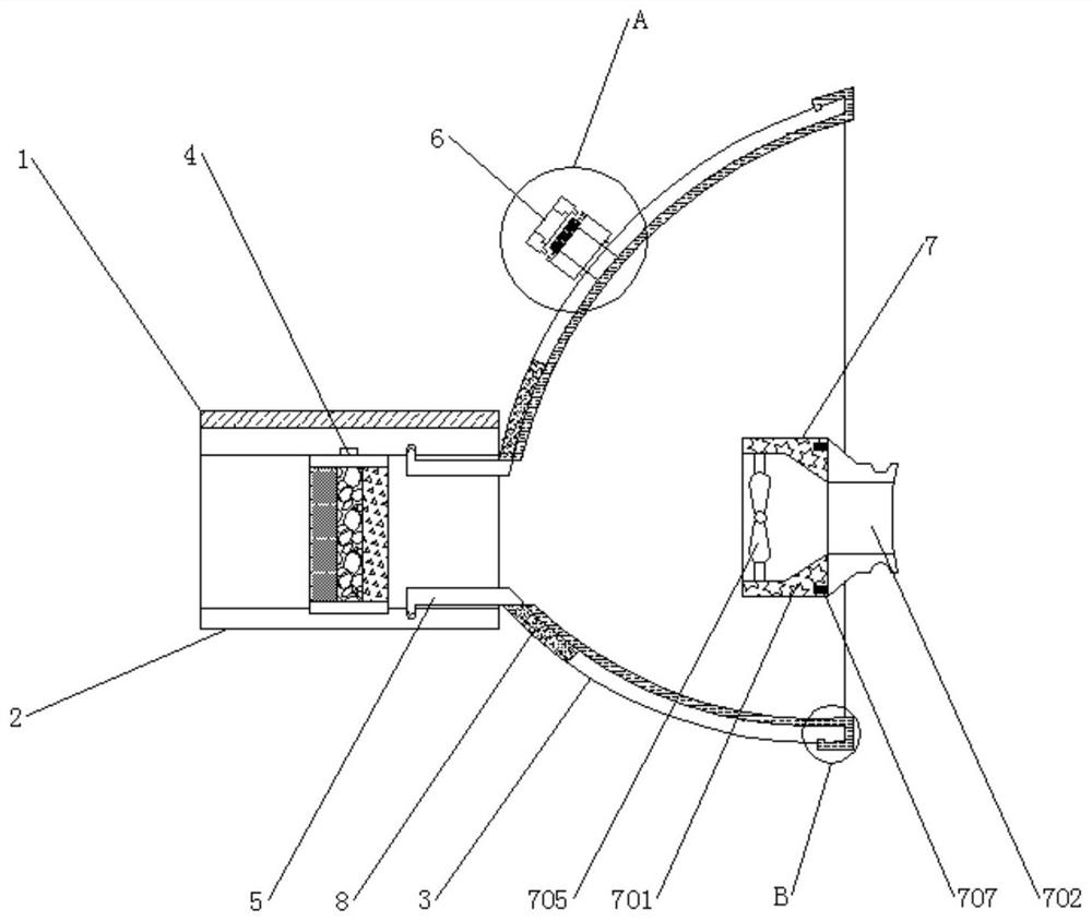
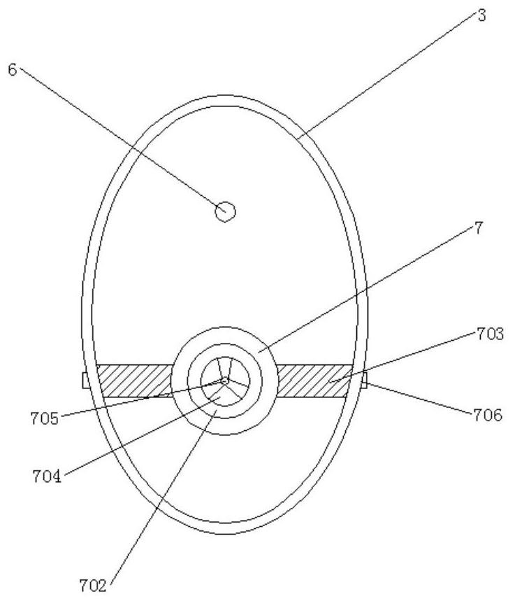
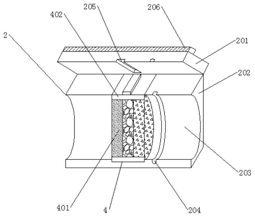
The invention discloses an isolation device for respiratory emergency and critical illness, which comprises a main body filter of the isolation device, a face mask, a vent hole and an anti-bite mouth. The other side of the main body of the isolation device is fixedly connected with a filter. It is connected with the outer peripheral wall on the other side of the main body of the isolation device. One side of the filter is movably connected to a mask, and the outer peripheral wall of the mask is connected to the inner wall of one side of the filter by overlapping. The top of the mask is fixedly connected with a vent hole, and the inside of the vent hole Placing the filter cotton can effectively absorb harmful gases, thereby preventing some untreated gas from being inhaled by the patient through the vent hole. At the same time, when the patient breathes, the filter cotton inside the vent hole will absorb the harmful gas exhaled by the patient. Adsorption, and the vent holes discharge other harmless gases to the outside, so as to prevent the harmful gases exhaled by patients from affecting other human bodies, which has broad development prospects in the future.
Description
An isolation device for respiratory emergency technical field [0001] The invention belongs to the technical field of medical devices, in particular to a respiratory emergency and critically ill isolation device. Background technique At present, when dealing with respiratory emergency, usually the patient's respiratory system is isolated from the outside air, and the Centralized air supply is used to prevent untreated air from being directly inhaled by the patient and aggravate the condition. At present, when the patient is isolated every time, every time the patient is active, the patient and the untreated The air is isolated, and it is easy to touch as long as you breathe, so it is impossible to properly isolate the untreated air when you isolate the air alone. The air is isolated from the patient, and when the isolation of acute and critical illness is unsuccessful, it will cause the patient to have difficulty breathing and close the mouth. However, the sudden cl...
Claims
Login to View More Application Information
Patent Timeline
 Patent Type & Authority Patents(China)
IPC IPC(8): A61M16/06
CPCA61M16/06A61M16/0683A61M16/0003
Inventor 郭小燕何万里孙红娟朱礼杰张裴刘文娟董颖
Owner SHANGQIU INST OF TECH
Features
- R&D
- Intellectual Property
- Life Sciences
- Materials
- Tech Scout
- Unparalleled Data Quality
- Higher Quality Content
- 60% Fewer Hallucinations
Learn More Browse by: Latest US Patents, China's latest patents, Technical Efficacy Thesaurus, Application Domain, Technology Topic, Popular Technical Reports.
© 2025 PatSnap. All rights reserved.Legal|Privacy policy|Modern Slavery Act Transparency Statement|Sitemap|About US| Contact US: help@patsnap.com