Multiphase disc type hybrid excitation flux switching motor
A magnetic flux switching motor and hybrid excitation technology, applied in the directions of motors, magnetic circuits, electromechanical devices, etc., can solve problems such as affecting the excitation efficiency of the excitation winding, and achieve the effects of simple structure, improved utilization, and wide adjustment of the magnetic field range.
- Summary
- Abstract
- Description
- Claims
- Application Information
AI Technical Summary
Problems solved by technology
Method used
Image
Examples
Embodiment 1
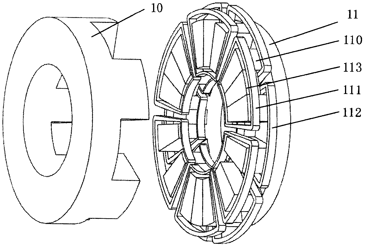
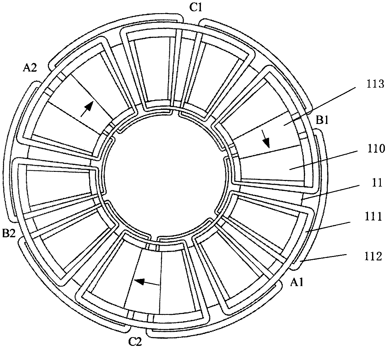
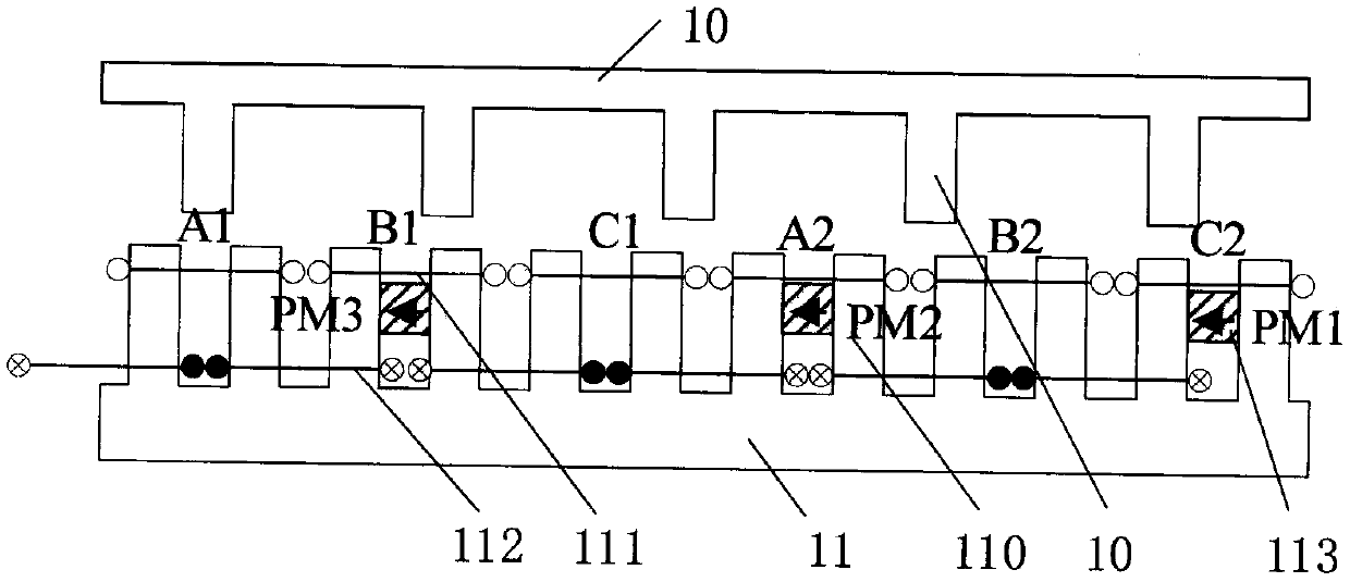
[0046] see figure 1 , a disc-type hybrid excitation flux switching motor of the present invention is composed of a stator core 11, a rotor core 10, an armature winding 111, an excitation winding 112 and a permanent magnet 113; the stator 11 and the rotor 10 are made of magnetically conductive materials Composed and has an air gap; the stator 11 is provided with stator magnetic teeth 110, there are slots between the stator magnetic teeth 110, part of the slots are provided with permanent magnets 113, and the stator magnetic teeth 110 are alternately arranged with concentrated armature windings 111 and concentrated excitation winding 112. In the motor of this embodiment, m=3, n=1, k=1, q=1, wherein, m is the phase number of the motor, n is the number of motor units, and k is a phase armature winding in each stator motor unit The logarithm of the concentrated armature windings 111 connected in series, q is a coefficient determining the number of permanent magnets, and the value ...
Embodiment 2
[0052] Figure 4 It is a disc type hybrid excitation flux switching motor. In this embodiment, m=3, n=2, k=1, q=1. The difference from the motor in Embodiment 1 is that the number of motor units on the stator 11 of this embodiment is n=2. That is, the motor is a three-phase motor with three phases A, B, and C, and includes 2 motor units, each motor unit has k=1 pair of concentrated armature windings, and the number of stator 11 magnetically conductive teeth 110 is Ns =4*m*n*k=24; the number of concentrated armature windings 111 arranged in turn on the magnetically conductive teeth is 2*m*n*k=12, and each concentrated armature winding 111 spans two magnetically conductive teeth 110 , the adjacent concentrated armature windings 111 share one slot; 2*m*k*n=12 concentrated excitation windings 112 are arranged in turn in the remaining 2*m*k*n=12 slots, and each concentrated excitation winding 112 spans Two adjacent magnetically conductive teeth 110 share a slot for every two con...
Embodiment 3
[0057] Figure 7 It is a disc type hybrid excitation flux switching motor. In this embodiment, m=3, n=2, k=1, q=2. The difference from the motor of Embodiment 2 is that the number of permanent magnets 113 on the stator 11 of this embodiment is m*q=6, which are evenly embedded in the axial inner part of the excitation slot, and the interval between every two permanent magnets is 4*k* n / q=4 stator magnetically permeable teeth 110 . The magnetization direction of all the permanent magnets 113 is along the same circumferential tangent direction, and is opposite to the direction of the magnetic field generated by the excitation coil in the excitation slot.
[0058] In this example, if Figure 8 As shown, the number and arrangement of motor windings are the same as those in Embodiment 2, and the flux linkage change and counter electromotive force in the three-phase windings have the same characteristics as Embodiment 2. The number of permanent magnet blocks is doubled compared t...
PUM
 Abstract
Description
Claims
Application Information
 - Generate Ideas
- Intellectual Property
- Life Sciences
- Materials
- Tech Scout
- Unparalleled Data Quality
- Higher Quality Content
- 60% Fewer Hallucinations
Browse by: Latest US Patents, China's latest patents, Technical Efficacy Thesaurus, Application Domain, Technology Topic, Popular Technical Reports.
© 2025 PatSnap. All rights reserved.Legal|Privacy policy|Modern Slavery Act Transparency Statement|Sitemap|About US| Contact US: help@patsnap.com


