
Robotic automatic welding device for submerged arc welding in space arc path

A technology of automatic welding and submerged arc welding, which is applied to the device supporting electrode clips, welding equipment, welding accessories, etc., can solve the problems of no economic benefit, poor fusion, inability to realize arbitrary arc changes of the path, etc., and achieves manual labor intensity. The effect of reducing, improving welding quality and improving welding efficiency

Active Publication Date: 2021-05-18
SHANGHAI ZPMC ELECTRIC +1
View PDF8 Cites 0 Cited by
  • Summary
  • Abstract
  • Description
  • Claims
  • Application Information

AI Technical Summary

Problems solved by technology

[0003] Regarding the submerged arc welding curve path weld, there are usually the following three technical problems. First, the planning of the path, the path of the trolley is mainly spliced ​​in a straight line, so it is impossible to achieve any arc change of the path. It is necessary to pre-plan the path turning position and turning speed on the path characteristic components. In order to ensure the stability of the welding process, it is necessary to ensure that the line speed is consistent and the rotation angle is smooth, so as to avoid the problem of poor fusion. Finally, the device with path offset can be independently The welding of a circular arc weld does not have good economic benefits from the perspective of automation
[0004] Welding devices for curved path welding components such as submerged arc welding and arc transition are rarely seen in the market and production at present

Method used


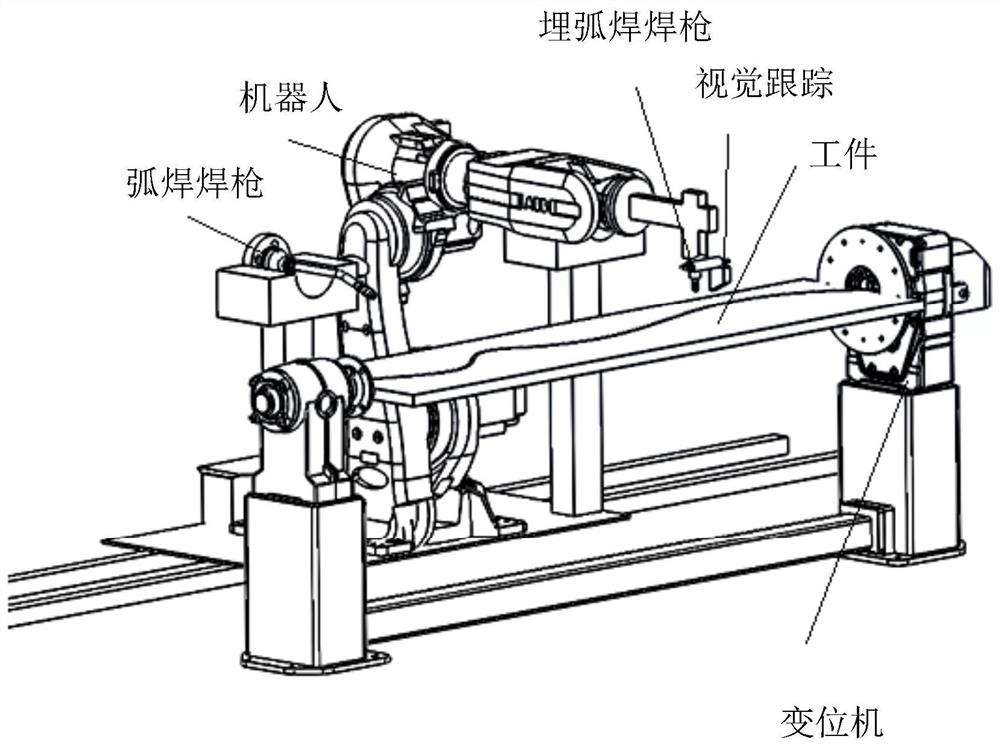
Image

  • Robotic automatic welding device for submerged arc welding in space arc path
  • Robotic automatic welding device for submerged arc welding in space arc path
  • Robotic automatic welding device for submerged arc welding in space arc path

Examples


Embodiment Construction

[0016] The technical solution of the present invention will be described in detail below in conjunction with the accompanying drawings.

[0017] The detailed features and advantages of the present invention are described in detail below in the specific embodiments, the content of which is sufficient to enable any person skilled in the art to understand the technical content of the present invention and implement it accordingly, and according to the specification, claims and drawings disclosed in this specification , those skilled in the art can easily understand the related objects and advantages of the present invention.

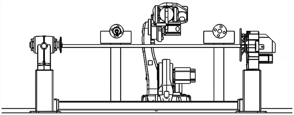
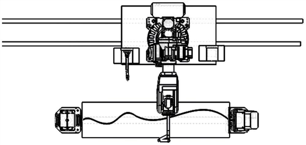
[0018] The present invention is mainly a robot welding device that can realize automatic welding of circular arc and space curve-like paths with multi-wire submerged arc with unclear roots. Tracking, automatic turn over and other functions. The device consists of a 6-axis manipulator, a quick automatic torch changer, a sliding table to expand the welding r...


PUM


Abstract

The invention discloses a robot automatic welding device for submerged arc welding in a space arc path, comprising: a robot system, a submerged arc welding machine system, a gas shielded arc welding system, a welding torch switching mechanism system, a laser vision tracking system, and a displacement machine system. A submerged arc welding torch and a laser vision tracking system are installed at the front end of the robot. The laser vision tracking system is set at an angle with the welding torch to realize real-time tracking and positioning of the welding workpiece and the weld seam during the welding process. The control device automatically identifies the corner characteristics of the welding path through the built-in corner path database, and invokes different multi-wire corner technologies corresponding to the corner characteristics to perform multi-wire welding on the arc path of the workpiece. The positioner system automatically completes the 180° turning of the welding workpiece. The device of the invention can weld the submerged arc welding of the straight line and the curved path, combines with the root cleaning process, improves the welding efficiency and welding quality, and reduces the labor intensity.

Description

technical field [0001] The present invention relates to the field of welding technology, and more particularly relates to a robot automatic welding device for submerged arc welding in a space arc path. Background technique [0002] The girder gusset plate of the quay bridge is the main load-bearing structural part of the quay bridge. Its main structural feature is that a member with an increased plate thickness is embedded in the main structure. Compared with the general structural connection requirements, it needs to bear greater tension and pressure. , so the design requires full penetration welding. Submerged arc welding is usually used in production. However, since the gusset plate is embedded into the main structure and the matching shape adopts a circular arc transition method, the commonly used trolley track cannot effectively match the path change. Therefore, The circular arc section of this type of welding structure requires manual repair welding, which greatly redu...

Claims


Application Information

Patent Timeline
IPC IPC(8): B23K9/18B23K9/16B23K9/28B23K9/32
CPCB23K9/16B23K9/18B23K9/287B23K9/32
Inventor 周军贾小磊黄建鹏钱丹李森
Owner SHANGHAI ZPMC ELECTRIC
Learn More