
Consumable box

A consumable box and cavity technology, applied in the direction of filtration and separation, hypodermic injection equipment, suction equipment, etc., can solve the problems of easy slipping or shaking, inconvenient installation and removal, inconvenient disassembly and installation, etc., to avoid slipping or shaking, Easy to assemble, easy to hold effect

Pending Publication Date: 2019-12-24
AMSINO MEDICAL (SHANGHAI) CO LTD
View PDF0 Cites 0 Cited by
  • Summary
  • Abstract
  • Description
  • Claims
  • Application Information

AI Technical Summary

Problems solved by technology

[0004] In the prior art, the consumables box connected to the waste collection device through the intubation tube is usually arranged on one or more collection ends on the casing or the top cover. The collection ends are arranged in parallel, and the ports face the same direction. The top cover of the consumables box is not easy Grab, rotate and unplug, not easy to install and remove
During the assembly process, the installation efficiency is reduced. During use, especially when sampling is required, it is inconvenient for the operator to remove and install the top cover of the consumable box. At the same time, the operator can only operate through the smooth shell, which is easy to slip or shake. , resulting in tissue spillage and contamination
In addition, since the top cover and the filter device are connected separately, it is not allowed to move the filter device during the sampling process, which is inconvenient for off-site sampling, especially for the analysis of large sample volume, which will cause great inconvenience to the sampling of medical staff. Change
At the same time, during the sampling process, since the waste is not always enclosed in the filter device but exposed to the outside, there is still a risk of waste overflowing when the top cover of the consumable box is slipped or shaken.

Method used


Image

  • Consumable box
  • Consumable box
  • Consumable box

Examples


Embodiment Construction

[0049] The following descriptions of the various embodiments refer to the accompanying drawings to illustrate specific embodiments that the present invention can be implemented in. The directional terms mentioned in the present invention, such as "up", "down", "front", "back", "left", "right", "inside", "outside", "side", etc., are for reference only The orientation of the attached schema. Therefore, the directional terms used are used to illustrate and understand the present invention, but not to limit the present invention.

[0050] The following descriptions of the various embodiments refer to the accompanying drawings to illustrate specific embodiments that the present invention can be implemented in. The directional terms mentioned in the present invention, such as "up", "down", "front", "back", "left", "right", "inside", "outside", "side", etc., are for reference only The orientation of the attached schema. Therefore, the directional terms used are used to illustrate ...


PUM


Abstract

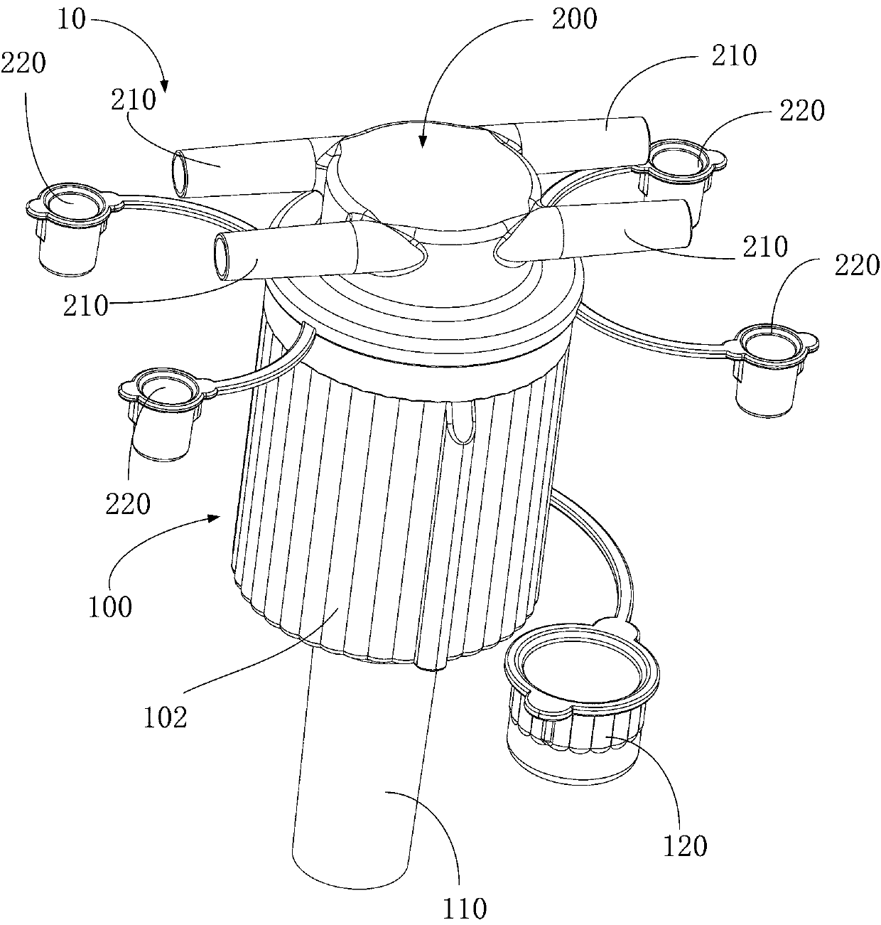
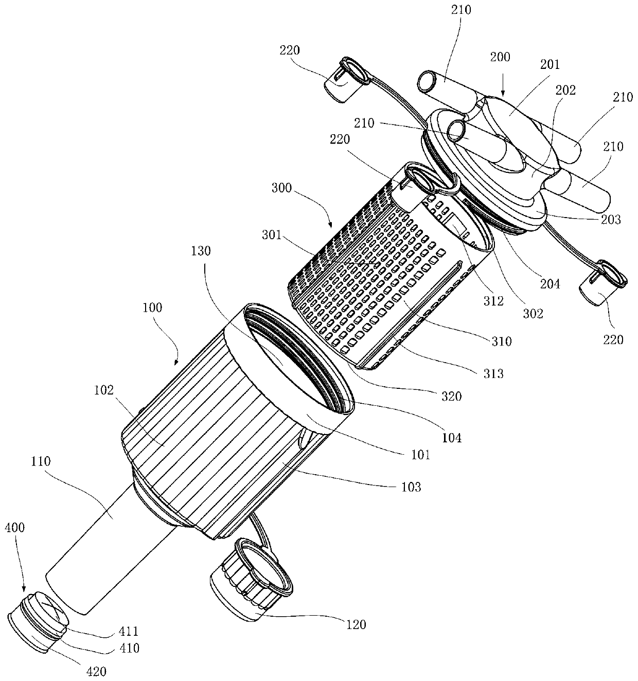
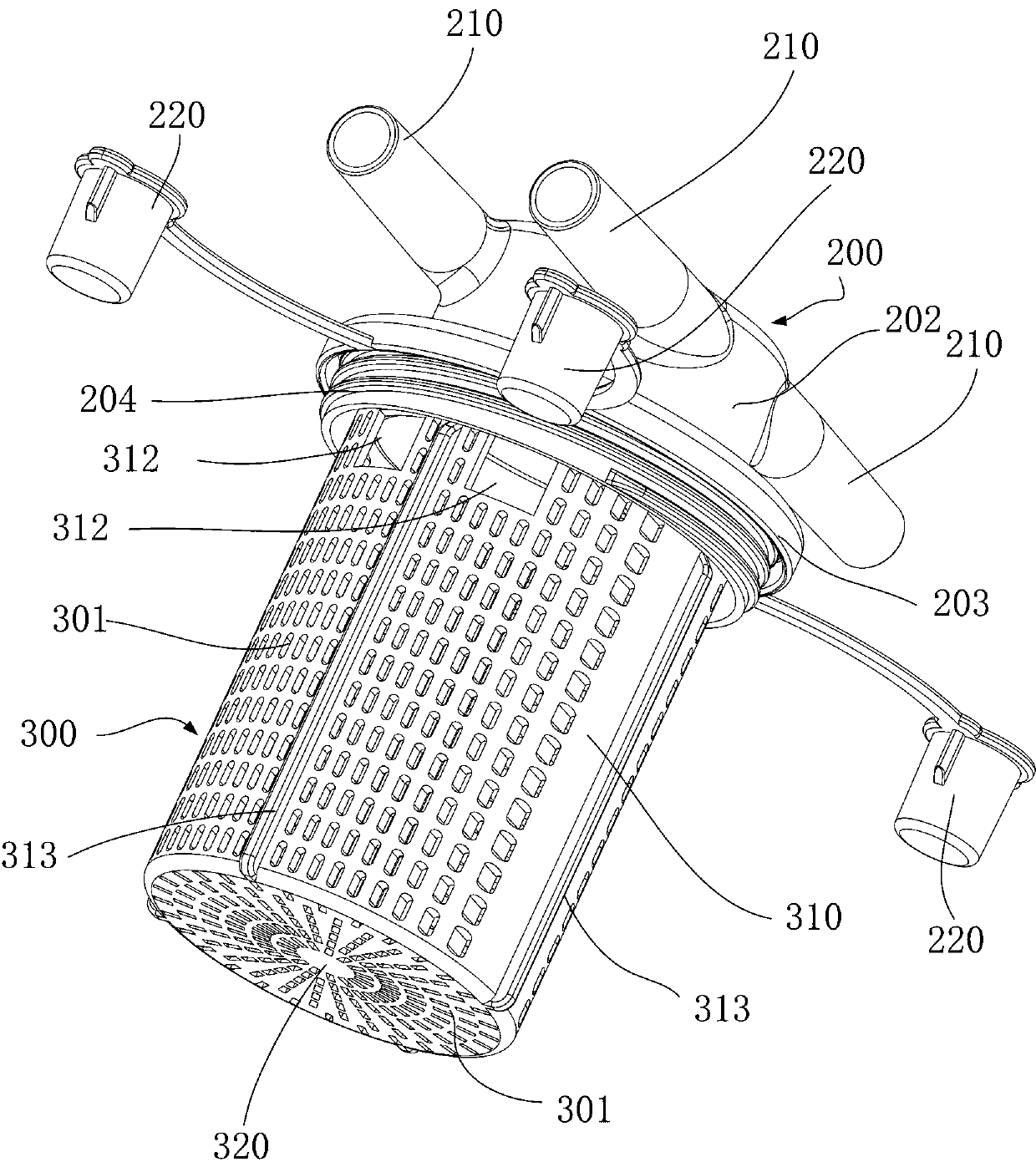
The embodiment of the invention provides a consumable box. The consumable box is used in a medical waste liquid collection device, and includes a base, at least one collecting end, a filter device anda top cover, wherein a shell of the base forms a first cavity and a discharge end used for connecting the medical waste liquid collection device and discharging medical waste liquid in the first cavity to the discharge end of the medical waste liquid collection device, the collecting ends are used for connecting an external suction pipeline and importing the medical waste liquid into the collecting ends of the first cavity, the filter device is arranged in the first cavity and used for filtering the medical waste liquid imported from the collecting ends, the top cover is detachably installedon the base, and is provided with a hand-held structure for disassembling or installing the top cover. According to the embodiment, the top cover of the consumable box is provided with the hand-held structure, so that the top cover is convenient to install and disassemble, easy to assembly, and convenient to disassemble and install at a sampling stage.

Description

technical field [0001] The invention relates to the field of medical equipment, in particular to a consumable box used for medical waste liquid collection equipment. Background technique [0002] During the implementation of specific surgical procedures, liquid, semi-solid, and solid wastes will inevitably be produced, including body fluids, such as blood, and perfusion solutions introduced into the surgical site during the surgical process. The resulting solid and semi-solid waste includes tissue fragments and small pieces of surgical material that may remain on body parts. Ideally, waste fluid is collected as it is generated so that it neither contaminates the surgical site nor becomes a biohazard in the operating room or other place where surgical procedures are performed. [0003] In the prior art, there are various waste liquid collection systems for medical personnel to collect the waste liquid generated during the operation or after the operation. Its principle is m...

Claims


Application Information

Patent Timeline
Patent Type & Authority Applications(China)
IPC IPC(8): A61M1/00B01D35/02
CPCA61M1/0001A61M1/0023A61M1/79A61M1/88A61M1/882B01D35/02
Inventor 周克东栗亚
Owner AMSINO MEDICAL (SHANGHAI) CO LTD
Learn More