
Uninterrupted plunger drainage gas recovery device and uninterrupted plunger drainage gas recovery method

A technology of drainage gas production and plunger, which is applied in the fields of production fluid, earthwork drilling, wellbore/well components, etc., can solve the problems of low gas production efficiency, difficult to take out the plunger, short production time, etc. Reasonable structure and the effect of reducing salvage depth

Inactive Publication Date: 2019-12-20
CNPC XIBU DRILLING ENG +1
View PDF5 Cites 2 Cited by
  • Summary
  • Abstract
  • Description
  • Claims
  • Application Information

AI Technical Summary

Problems solved by technology

[0003] The invention provides an uninterrupted plunger drainage gas recovery device and an uninterrupted plunger drainage gas recovery method, which overcome the above-mentioned deficiencies in the prior art, and can effectively solve the problems caused by frequent well shut-in in the existing plunger drainage gas recovery. The problem of short production time and low gas production efficiency; it can further solve the problem that the existing plunger is not easy to take out from the blowout preventer

Method used


Image

  • Uninterrupted plunger drainage gas recovery device and uninterrupted plunger drainage gas recovery method
  • Uninterrupted plunger drainage gas recovery device and uninterrupted plunger drainage gas recovery method
  • Uninterrupted plunger drainage gas recovery device and uninterrupted plunger drainage gas recovery method

Examples


Embodiment Construction

[0027] The present invention is not limited by the following examples, and specific implementation methods can be determined according to the technical solutions of the present invention and actual conditions.

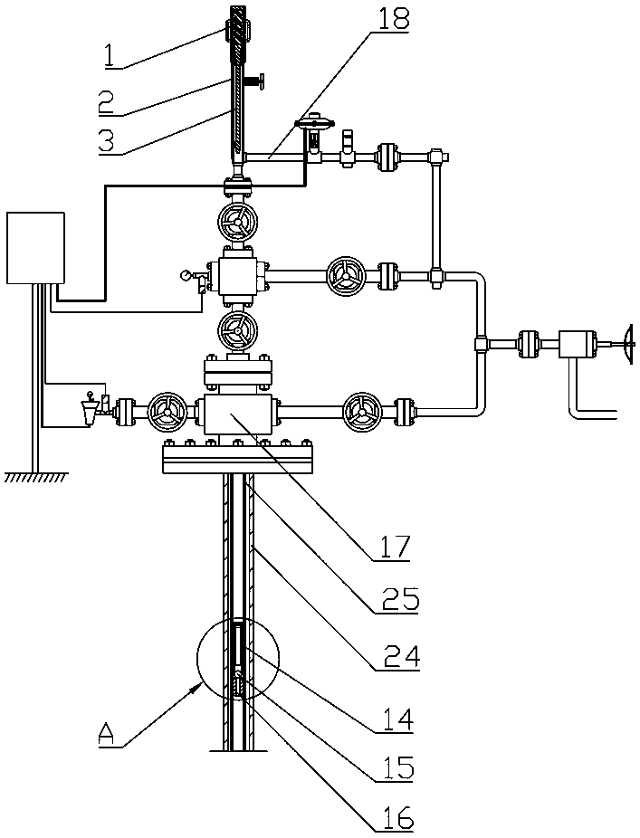
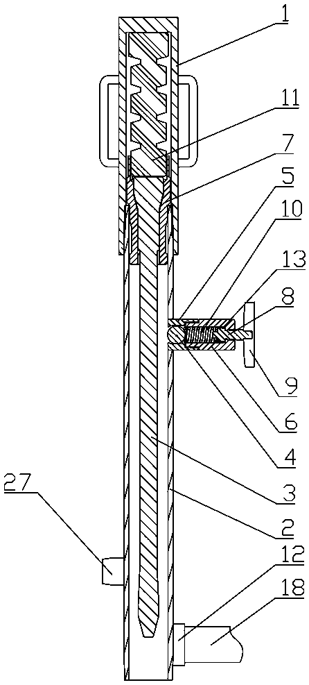
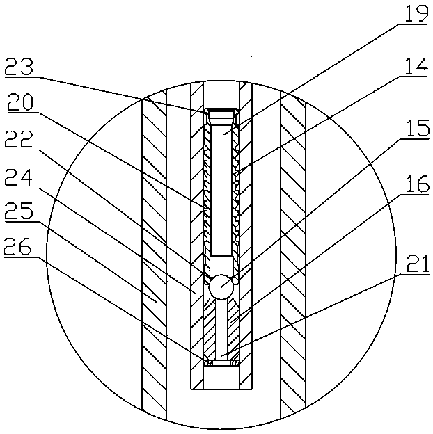
[0028] In the present invention, for the convenience of description, the description of the relative positional relationship of each component is based on the figure 1 For example, the positional relationship of front, back, up, down, left, right, etc. is based on the attached figure 1 determined by the layout direction.

[0029] Below in conjunction with embodiment and accompanying drawing, the present invention will be further described:

[0030] as attached figure 1 , 2, 3, the uninterrupted plunger drainage gas production device comprises a gas well 24, a gas production tree 17, a gas pipeline 18, a blowout preventer, a plunger body 14, a sealing ball 15 and a receiving pipe 16, and the gas well 24 is provided with The gas tree 17 is provided with a blowout pip...


PUM


Abstract

The invention relates to the technical field of gas recovery tools, in particular to an uninterrupted plunger drainage gas recovery device and an uninterrupted plunger drainage gas recovery method. The uninterrupted plunger drainage gas recovery device comprises a gas well, a gas recovery tree, a gas conveying pipeline, a blow-out control pipe, a plunger body, a sealing ball and an adapting pipe.The gas recovery tree is arranged on the gas well, and the blow-out control pipe is arranged above the gas recovery tree and comprises an upper hood, a lower pipe body, an inner bush, a center rod, abuffer rubber barrel and a pipeline joint. The uninterrupted plunger drainage gas recovery method comprises the following step that the adapting pipe, the sealing ball and the plunger body are sequentially put into an oil pipe in the gas well. According to the uninterrupted plunger drainage gas recovery device and the uninterrupted plunger drainage gas recovery method, the structure is reasonableand compact, and use is convenient; the plunger body and the sealing ball are separated through the center rod, and the sealing ball falls back into the well to cooperate with the adapting pipe to achieve well bottom pressure maintaining; after the well pressure is reduced, the plunger body falls back into the well to be recombined with the sealing ball; when the well bottom pressure is sufficient, the sealing body and the plunger body continue to be pushed to move upwards; operation is repeated in this way to achieve uninterrupted plunger drainage gas recovery work; and the advantages of rapidness, reliability and high efficiency are achieved.

Description

technical field [0001] The invention relates to the technical field of gas extraction tools, and relates to an uninterrupted plunger drainage gas extraction device and an uninterrupted plunger drainage gas extraction method. Background technique [0002] During the operation of traditional plunger drainage and gas production, the valves on the gas production tree need to be closed frequently, which requires a long time for shutting down the well and cannot provide uninterrupted production. Therefore, the problems of short production time and low single well production are caused, which affect the production efficiency of gas wells and cannot realize the efficient development of gas fields. On the other hand, the existing blowout preventer cannot meet the replacement requirements of the plunger, making it difficult to replace the plunger. fall to the valve plate of the main valve of the gas tree, and then use the salvage tool to salvage the plunger from the gas tree. Since t...

Claims


Application Information

Patent Timeline
Patent Type & Authority Applications(China)
IPC IPC(8): E21B43/00E21B43/12
CPCE21B43/00E21B43/121
Inventor 罗顺张贵仪乔东宇段文广赵继斌张胜鹏高冀新张国斌王飞跃王肃凯
Owner CNPC XIBU DRILLING ENG
Learn More