Annular thin-wall part forming method, forming mold and forming stamping tool

A forming method and forming mold technology, which are applied in the direction of manufacturing tools, forging/pressing/hammer devices, forging/pressing/hammering machinery, etc., can solve the problems of large forming resistance, low working life, and high energy consumption for the production of a single part. Achieve the effects of small forming resistance, improved working life and reduced production energy consumption

Active Publication Date: 2019-12-17
顺科智连技术股份有限公司
View PDF6 Cites 1 Cited by
  • Summary
  • Abstract
  • Description
  • Claims
  • Application Information

AI Technical Summary

Problems solved by technology

Since the direction of the cold heading impact force (arrow F) is opposite to the deformation direction of the head material (dashed arrow) during the "reverse extrusion", more material in the head needs to participate in the deformation, so that The forming resistance in the deformation process is relatively large, resulting in high energy consumption for the production of a single part. Correspondingly, the forming dies and forming punches used in the forming process also bear relatively large loads due to the large forming resistance, resulting in Its working life is low

Method used


Image

  • Annular thin-wall part forming method, forming mold and forming stamping tool
  • Annular thin-wall part forming method, forming mold and forming stamping tool
  • Annular thin-wall part forming method, forming mold and forming stamping tool

Examples


Embodiment Construction

[0038] Below, the present invention will be further described in conjunction with the accompanying drawings and specific implementation methods. It should be noted that, under the premise of not conflicting, the various embodiments described below or the technical features can be combined arbitrarily to form new embodiments. .

[0039] A method for forming an annular thin-walled part, which is applied to a columnar blank, is characterized in that the method for forming comprises the following steps:

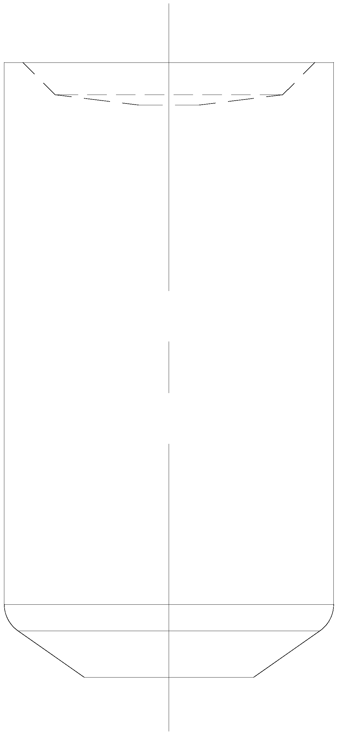
[0040] Material breaking steps: reference figure 1 , intercept a certain length of the initial billet segment.

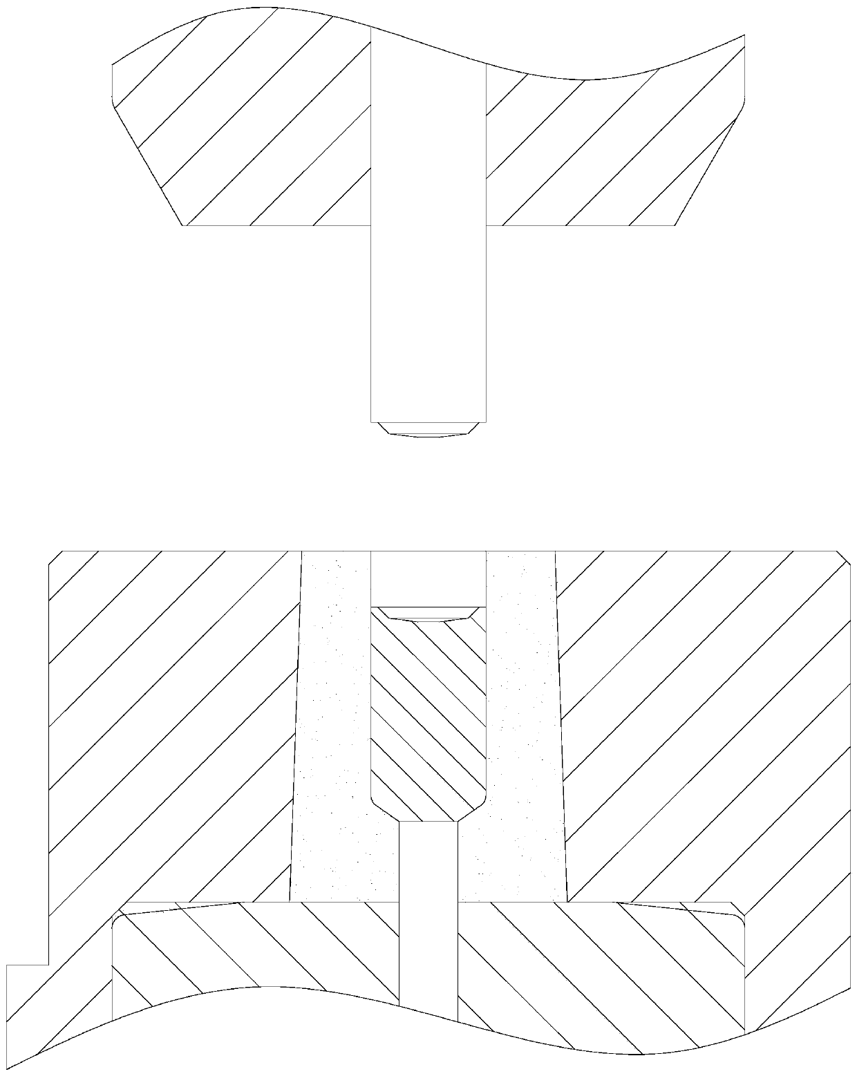
[0041] Shaping steps: reference Figure 1 to Figure 3 , the upper and lower ends of the initial blank section are shaped to smooth the cut marks on the upper and lower ends of the initial blank section.

[0042] Head Upsetting Steps: Reference Figure 3 to Figure 5 , Upsetting the upper end of the initial blank section to form the head 1, so that the initial blank...


PUM


Abstract

The invention discloses an annular thin-wall part forming method. The forming method is applied to a columnar blank material, and comprises the following steps of head part upsetting, hole extruding and thin-wall part extruding, wherein upsetting is conducted on one end of an initial blank material section to form a head part, the initial blank material section forms a stepped shaft-shaped blank material section, and hole upsetting is simultaneously conducted on the end surface of one end of the initial blank material section in the process of initial blank material section upsetting, so thatan initial positioning hole is formed in the end surface in the head part upsetting step; the initial positioning hole is extruded and stretched, so that the axial dimension of the stepped shaft-shaped blank material section becomes larger, in addition, the initial positioning hole becomes longer and forms a long positioning hole, and the axial dimension of the head part becomes larger, wherein the to-be-deformed volume required by a subsequently formed thin-wall part is reserved in the head part in the hole extruding step; and a circumferential surface part of the head part is extruded, so that a thin-wall part is formed for the head part in the thin-wall part extruding step. Due to the fact that the forming resistance of the forming method is small, the impact force borne by a cold unsetting mold is correspondingly small.

Description

technical field [0001] The invention relates to a forming method of an annular thin-walled part, a forming die and a forming punch. Background technique [0002] Compared Figure 9 and Figure 15 , the periphery of the head of some stepped shaft-shaped billet sections needs to be made with annular thin-walled parts 13. In the prior art, it is necessary to perform "back extrusion" on the head of the stepped shaft-shaped billet section so that The periphery of the head forms an annular thin-walled portion. The process is specifically to carry out cold heading at the middle position of the bottom side of the head near the shaft section (refer to Figure 15 middle arrow F) to move the material of the head along the Figure 15 Extruded in the direction of the dotted arrow in the middle to form an annular thin-walled part 13. Since the direction of the cold heading impact force (arrow F) is opposite to the deformation direction of the head material (dashed arrow) during the "r...

Claims


Application Information

Patent Timeline
IPC IPC(8): B21J5/00B21J13/02
CPCB21J5/002B21J13/02
Inventor 田忠轩孙裔良田明珠
Owner 顺科智连技术股份有限公司
Why Eureka
Try Eureka