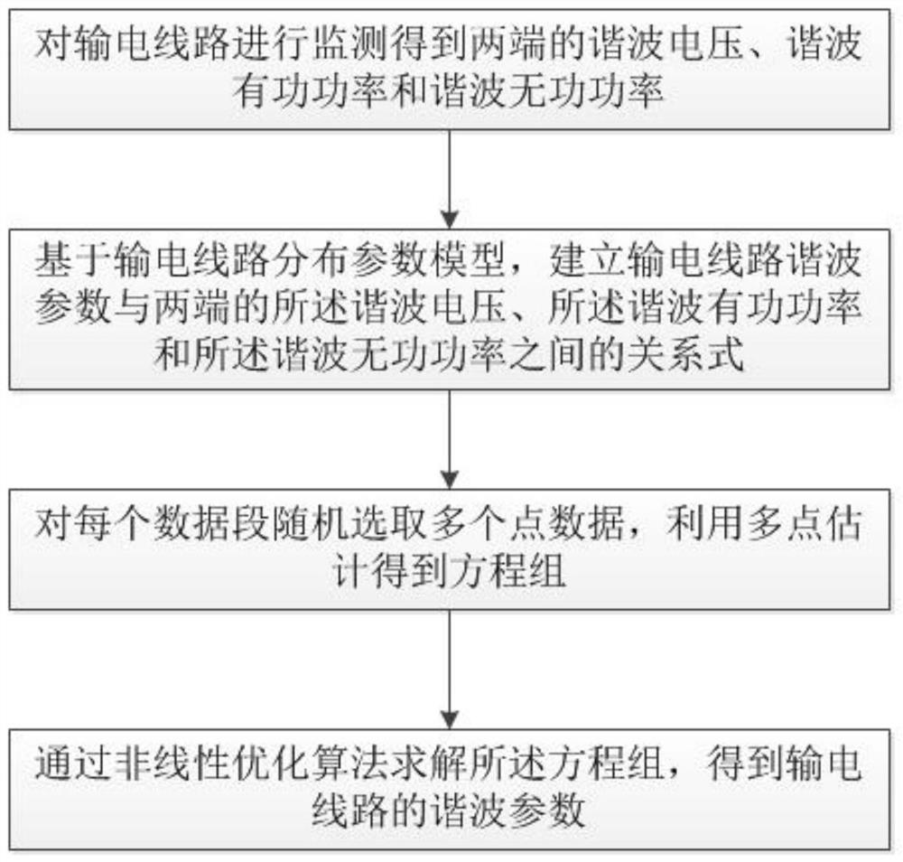
A transmission line harmonic parameter estimation method for power grid harmonic analysis
A transmission line and harmonic analysis technology, applied in the field of power system, can solve the problem of inaccurate parameter estimation, and achieve the effect of simple calculation and small parameter estimation error.
- Summary
- Abstract
- Description
- Claims
- Application Information
AI Technical Summary
Problems solved by technology
Method used
Image
Examples
Embodiment 1
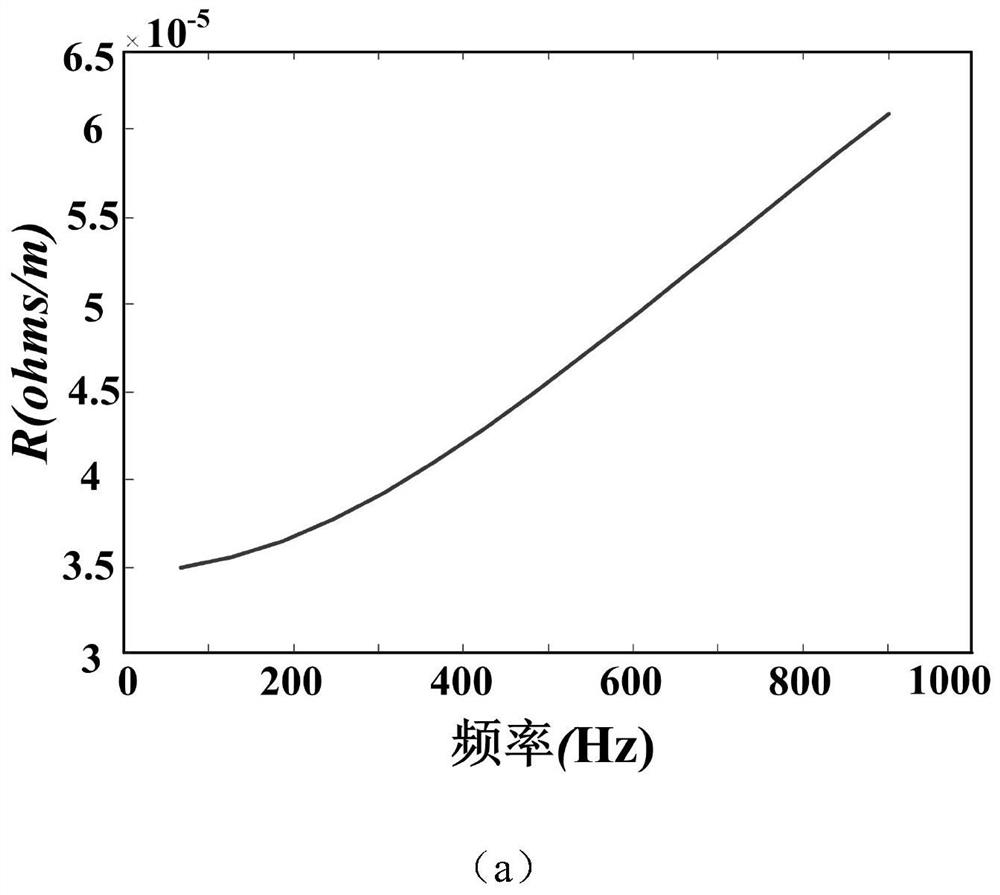
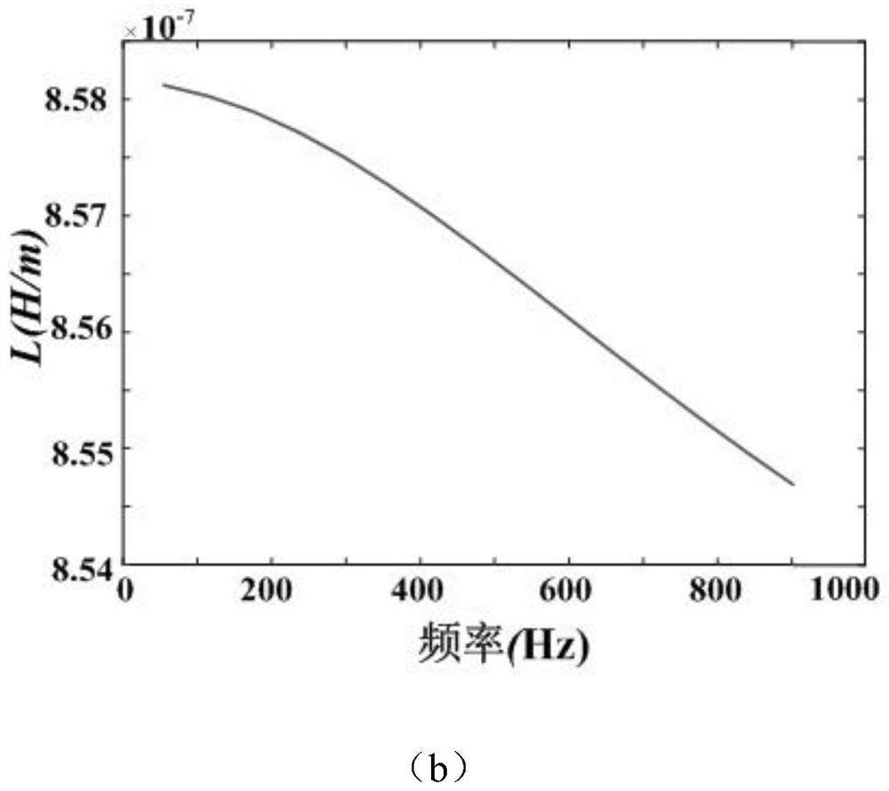
[0086] Use PSCAD to simulate and verify a 500kV transmission line with a length of 300km. The parameter settings are shown in Table 1. The effective value of each equivalent harmonic voltage source at the sending end is set to 1% of the effective value of the fundamental voltage. The exact value of the harmonic parameters of the transmission line is extracted from the parameter file output by PSCAD. The simulation time is 24h, and the sampling interval is 5s, with a total of 17280 simulation data.
[0087] Table 1 Simulation model parameter settings
[0088]
[0089] The first step is to obtain the harmonic voltage, active power and reactive power values at both ends of the transmission line. In this simulation case, the third harmonic voltage, active power and reactive power values are as follows Figure 5 shown.
[0090] In the second step, the data is randomly sampled and grouped. The 10-minute sampling data is 120 points, and 10 points are randomly sampled as a gro...
Embodiment 2
[0097] The traditional harmonic parameter estimation of transmission lines ignores the equivalent parallel conductance. When there is corona loss in the transmission line, and considers the distributed parameter model (interaction among the four parameters), ignores the G 0 It may reduce the estimation accuracy of other parameters. Therefore, on the basis of Calculation Example 1, considering the corona loss of the transmission line is 5kW / km (G 0 =0.0015), the calculation error is shown in Table 3,
[0098] Table 3 Embodiment 2 calculation error
[0099]
[0100] It can be seen from Table 3 that the traditional method estimates the equivalent parallel resistance and conductance of the transmission line with relatively large errors, and the calculation errors of the equivalent conductance at all harmonic frequencies are relatively high, while the calculation errors of each parameter of the method proposed by the present invention are all large. Within 5%. It can be concl...
PUM
 Abstract
Description
Claims
Application Information
 - R&D Engineer
- R&D Manager
- IP Professional
- Industry Leading Data Capabilities
- Powerful AI technology
- Patent DNA Extraction
Browse by: Latest US Patents, China's latest patents, Technical Efficacy Thesaurus, Application Domain, Technology Topic, Popular Technical Reports.
© 2024 PatSnap. All rights reserved.Legal|Privacy policy|Modern Slavery Act Transparency Statement|Sitemap|About US| Contact US: help@patsnap.com


