Placing rack with lifting and stretching functions for network platform

A technology of network platform and rack, which is applied in the direction of machines/stands, supporting machines, mechanical equipment, etc., can solve the problems of mutual interference of network equipment, waste of equipment racks, occupying placement, etc., to ensure network transmission function, guarantee The effect of placing in size and height and saving space

Inactive Publication Date: 2019-12-13
徐州市贾汪区新源众创科技孵化器有限公司
View PDF6 Cites 0 Cited by
  • Summary
  • Abstract
  • Description
  • Claims
  • Application Information

AI Technical Summary

Problems solved by technology

[0002] Network platform placement rack, the function of the placement rack is to save space as the primary requirement. The safe use and effective placement of the placement rack may be suitable for placing more network equipment at the same time. In the current stage of network equipment The use of the display rack is fixed and has a single function. The use of multiple network devices requires more placement space, making it impossible to place network devices in the only space, or they may be stacked and used to cause slipping or It is the effect of network equipment causing mutual interference, which is not conducive to better use of network equipment. The use of different equipment sizes and heights cannot be realized, making it necessary to replace other supporting equipment racks for use, resulting in poor equipment racks. necessary waste

Method used


Image

  • Placing rack with lifting and stretching functions for network platform
  • Placing rack with lifting and stretching functions for network platform
  • Placing rack with lifting and stretching functions for network platform

Examples


Embodiment Construction

[0013] The present invention will be further described below in conjunction with the accompanying drawings.

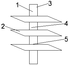
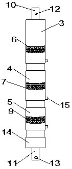
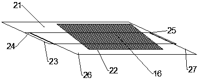
[0014] Such as Figure 1 to Figure 3 As shown, the present invention is a placement rack with a lifting and stretching function for a network platform, including a lifting spindle 1 and three stretching bearing plates 2, and the lifting spindle 1 includes a lifting rod I3, a lifting rod II4, and a lifting rod III5 , the first rotating snap ring 6, the second rotating snap ring 7 and the third rotating snap ring 9, the surface of the lifting rod I3 is buckled to connect with the first rotating snap ring 6, and the surface of the lifting rod II4 is buckled to connect with the second rotating snap ring. The snap ring 7, the surface of the lifting rod III 5 is buckled and connected to the third rotating snap ring 9, and the surfaces of the first rotating snap ring 6, the second rotating snap ring 7 and the third rotating snap ring 9 are respectively fixedly connected to th...


PUM


Abstract

The invention provides a placing rack with lifting and stretching functions for a network platform. The placing rack comprises a lifting main shaft and three stretching bearing plates; the lifting main shaft comprises a lifting rod I, a lifting rod II, a lifting rod III, a first rotating snap ring, a second rotating snap ring and a third rotating snap ring; the surface of the lifting rod I is connected with the first rotating snap ring in a bucking manner; the surface of the lifting rod II is connected with the second rotating snap ring in a buckling manner; the surface of the lifting rod IIIis connected with the third rotating snap ring in a buckling manner; the surfaces of the first rotating snap ring, the second snap ring and the third snap ring are correspondingly and fixedly connected with the stretching bearing plates; the inner part of the bottom side of the lifting rod I is arranged in a hollow structure; the bottom end of the lifting rod I is connected with the surface of theupper part of the lifting rod II in an embedding manner; the surface of the inner wall at the lower part of the lifting rod II is arranged in a hollow structure; the bottom end of the lifting rod IIis connected to the surface of the upper part of the lifting rod III in an embedding manner; and the surface of the top end of the lifting main shaft is fixedly connected with a fixed plate.

Description

technical field [0001] The invention relates to a shelf for a network platform with lifting and stretching functions, belonging to the field of shelf for the network platform. Background technique [0002] Network platform placement rack, the function of the placement rack is to save space as the primary requirement. The safe use and effective placement of the placement rack may be suitable for placing more network equipment at the same time. In the current stage of network equipment The use of the display rack is fixed and has a single function. The use of multiple network devices requires more placement space, making it impossible to place network devices in the only space, or they may be stacked and used to cause slipping or It is the effect of network equipment causing mutual interference, which is not conducive to better use of network equipment. The use of different equipment sizes and heights cannot be realized, making it necessary to replace other supporting equipmen...

Claims


Application Information

Patent Timeline
Patent Type & Authority Applications(China)
IPC IPC(8): F16M11/28F16M11/02
CPCF16M11/02F16M11/28
Inventor 吴庆补
Owner 徐州市贾汪区新源众创科技孵化器有限公司
Why Eureka
Try Eureka