Liftable ballastless track structure and adjustment method thereof

A ballastless track and track slab technology, applied in the direction of tracks, roads, ballast layers, etc., can solve the problem of threatening the safe operation of high-speed railways, many railway speed limit stations, and it is difficult to meet large deformation and long duration in special areas Adjust demand and other issues to achieve the effect of saving operation and maintenance costs, reducing the number of outages and overhauls, and facilitating installation operations

Pending Publication Date: 2019-12-13
CHINA RAILWAY ERYUAN ENG GRP CO LTD
View PDF0 Cites 4 Cited by
  • Summary
  • Abstract
  • Description
  • Claims
  • Application Information

AI Technical Summary

Problems solved by technology

[0003] The purpose of the present invention is to overcome the above-mentioned shortcomings such as the ballastless track structure in the prior art is difficult to meet the large deformation and long-duration adjustment requirements in special areas, so that there are many railway speed limit stations, which threaten the safe operation of high-speed railways, etc. Provide a liftable ballastless track structure and its adjustment method

Method used


Image

  • Liftable ballastless track structure and adjustment method thereof
  • Liftable ballastless track structure and adjustment method thereof
  • Liftable ballastless track structure and adjustment method thereof

Examples


Embodiment 1

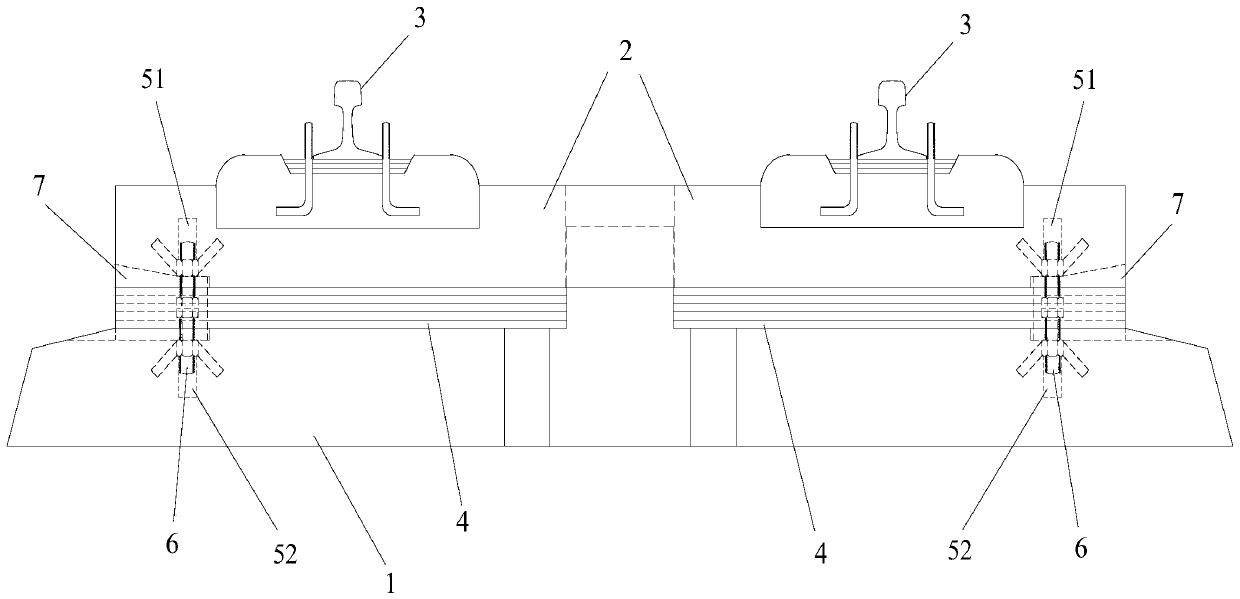
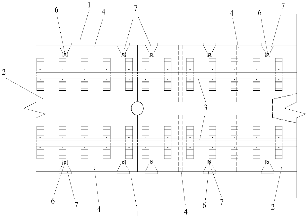
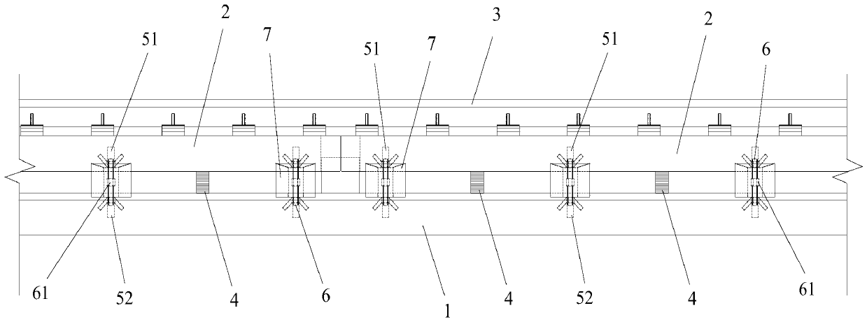
[0035] Such as Figure 1-3 As shown, a liftable ballastless track structure according to the present invention includes a base 1, a track plate 2 and two rails 3, and several track plates 2 are spliced ​​to form an integral track plate, and the two rails 3 Set on the integral track plate.

[0036]Specifically, the bottom surface of each track plate 2 is provided with a vertical channel one 51, the opening of the channel one 51 is downward, and each channel one 51 is located on the outside of the rail 3, that is, away from the track One side of the center line of the plate 2, the top surface of the base 1 is provided with a vertical channel two 52, the opening of each channel two 52 is upward, and the shape and position of each channel one 51 are consistent with one of the channels. The shape and position of the second channel 52 are adapted, and the specific size and quantity are determined according to the design requirements. For example, each track plate 2 is provided with...

Embodiment 2

[0042] A method for adjusting a liftable ballastless track structure according to the present invention includes using a liftable ballastless track structure as described in Embodiment 1, comprising the following steps:

[0043] a. Take out the block 7 between the base 1 and the track plate 2;

[0044] b. When it is necessary to increase the elevation of the track plate 2, first turn the transmission rod 6 to raise the track plate 2 to 10-15mm higher than the target elevation, then make the height of the pad 4 meet the target elevation of the track plate 2, and then reverse Rotate the transmission rod 6 to lower the track plate 2 to the target elevation, and abut against the top surface of the pad 4; The track plate 2 rises, and then the height of the spacer 4 meets the target elevation of the track plate 2, and then the transmission rod 6 is reversely rotated to lower the track plate 2 to the target elevation, and the spacer 4 is connected to the target elevation. top abutme...


PUM


Abstract

The invention discloses a liftable ballastless track structure and an adjustment method thereof. According to the liftable ballastless track structure, a left-handed nut and a right-handed nut on eachtransfer bar are relatively close to each other or relatively far away from each other by driving an adjusting nut, and thus, the distances between a track plate connected to the left-handed nut anda base and between a track plate connected the right-handed nut and the base are increased or decreased; and a gap between each track plate and the base is supported by arranging a cushion block. Theliftable ballastless track structure can break through the adjustable range limiting value of the prior art, effectively adapts to a large number of continuous arching or settlement deformation in special areas such as road cutting in expansive rock and soil areas, has high adjustment accuracy, is especially suitable for the accuracy control of uphill and downhill lines and curved lines, effectively reduces the speed-limiting operation sites of railways, ensures the speed of railway operation, increases the safety factors of railway operation, reduces the frequency of outage for overhauling, saves operation and maintenance costs, is convenient for initial installation operation and elevation adjustment operation, and has good application prospect.

Description

technical field [0001] The invention relates to the technical field of railway track maintenance, in particular to a liftable ballastless track structure and an adjustment method thereof. Background technique [0002] The adjustment of deformation of ballastless track of high-speed railway is mainly realized by fasteners. The deformation adjustment ability of existing standard fasteners is weak, and the total adjustment amount does not exceed 40mm, that is, 25mm upward and 15mm downward. Speed-limited operation or maintenance of the track structure will inevitably result in huge maintenance costs and operating losses. In some specific areas, such as regional settlement, expansive rock, soft rock deep cutting and other areas, the long-term continuous deformation of the foundation is difficult to control, especially It is a deep cutting in expansive rock and soil. Due to comprehensive factors such as expansibility and soft rock rheology, continuous long-term arching deformatio...

Claims


Application Information

Patent Timeline
Patent Type & Authority Applications(China)
IPC IPC(8): E01B1/00E01B3/00
CPCE01B1/002E01B3/00
Inventor 吴沛沛钟志彬邓荣贵李安洪周其健王园园孙怡张晋刘远程胡会星张敏任华锋刘剑光许益国李尧
Owner CHINA RAILWAY ERYUAN ENG GRP CO LTD
Why Eureka
Try Eureka