On-line calibration method of field gas density relay
A technology of gas density and calibration method, applied in the field of electric power, can solve problems such as potential safety hazards, hazards, flashovers, etc.
- Summary
- Abstract
- Description
- Claims
- Application Information
AI Technical Summary
Problems solved by technology
Method used
Image


Examples
Embodiment 1
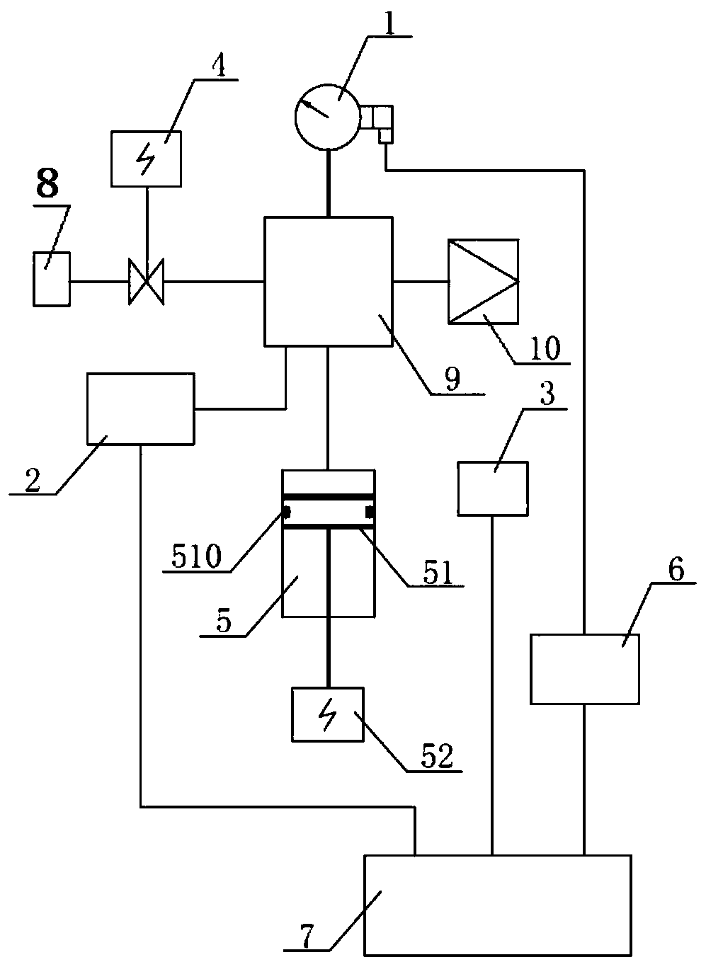
[0141] Such as figure 1 As shown, Embodiment 1 of the present invention provides an on-line verification method for an on-site gas density relay. Specifically, one end of the electric control valve 4 is sealed and connected to the electrical equipment, and the other end of the electric control valve 4 is passed through The multi-way joint 9 communicates with the gas density relay body 1; the pressure sensor 2 communicates with the gas density relay body 1 on the gas path through the multi-way joint 9; the pressure adjustable mechanism 5 communicates with the gas density relay body 1 through the multi-way joint 9. The relay body 1 is connected; the online verification contact signal sampling unit 6 is respectively connected with the gas density relay body 1 and the intelligent control unit 7; the electric control valve 4, the pressure sensor 2, the temperature sensor 3 and the pressure adjustable mechanism 5 are respectively It is connected with the intelligent control unit 7; ...
Embodiment 2
[0165] Such as image 3 As shown, an on-site gas density relay calibration method provided by Embodiment 2 of the present invention includes: a gas density relay body 1, a pressure sensor 2, a temperature sensor 3, an electric control valve 4, a pressure adjustable mechanism 5, an online Calibration contact signal sampling unit 6, intelligent control unit 7, multi-way joint 9, air supply interface 10, self-sealing valve 11. One end of the self-sealing valve 11 is sealingly connected to the electrical equipment, and the other end of the self-sealing valve 11 is in communication with the electric control valve 4; one end of the self-sealing valve 4 is sealingly connected to the self-sealing valve 11, and the electric The other end of the control valve 4 is connected with a multi-way joint 9 . The gas density relay body 1 is installed on the multi-way joint 9; the pressure sensor 2 and the temperature sensor 3 are arranged on the gas density relay body 1, and the pressure sensor...
Embodiment 3
[0168] Such as Figure 4 As shown, an on-site gas density relay calibration method provided by Embodiment 3 of the present invention includes: gas density relay body 1, pressure sensor 2, temperature sensor 3, electric electronic control valve 4, pressure adjustable mechanism 5, On-line verification contact signal sampling unit 6, intelligent control unit 7, multi-way joint 9, air supply interface 10, valve 12. One end of the valve 12 is sealingly connected to the electrical equipment, and the other end of the valve 12 is in communication with the electric control valve 4; one end of the electric control valve 4 is sealingly connected to the valve 12, and the electric control valve 4 The other end of the multi-way joint 9 is connected. The gas density relay body 1 is installed on the multi-way joint 9; the pressure sensor 2, the temperature sensor 3, the online verification contact signal sampling unit 6 and the intelligent control unit 7 are set together. The pressure adjus...
PUM
 Abstract
Description
Claims
Application Information
 - R&D
- Intellectual Property
- Life Sciences
- Materials
- Tech Scout
- Unparalleled Data Quality
- Higher Quality Content
- 60% Fewer Hallucinations
Browse by: Latest US Patents, China's latest patents, Technical Efficacy Thesaurus, Application Domain, Technology Topic, Popular Technical Reports.
© 2025 PatSnap. All rights reserved.Legal|Privacy policy|Modern Slavery Act Transparency Statement|Sitemap|About US| Contact US: help@patsnap.com