power generation device

A technology for power generation devices and generator sets, applied in wind power generation, photovoltaic power generation, renewable energy power generation, etc., can solve the problems of reduced wind area of ​​fans, increase of wind area of ​​fans, and low utilization rate of wind energy, etc. The effect of reducing the area of ​​the ground, reducing the burn of the battery board, and improving the overall power generation

Active Publication Date: 2021-11-23
靳军
View PDF13 Cites 0 Cited by
  • Summary
  • Abstract
  • Description
  • Claims
  • Application Information

AI Technical Summary

Problems solved by technology

At present, there are many new wind power generator patents for controlling the overspeed rotation of fans, such as CN 102094761 A, which discloses a wind power generator with a vertical axis, but the wind receiving area of ​​its blades is extremely limited, and the wind energy in the start-up stage The utilization rate is low; when the wind speed is high, the centrifugal force is used to expand the blades outward, increasing the moment of inertia, and limiting the speed to prevent the fan from rotating overspeed
However, this method cannot reduce the wind receiving area of ​​the fan to zero, so it cannot fundamentally solve the problem of overspeeding of the fan in strong wind or stormy weather, and this method will also increase the overall lateral wind receiving area of ​​the fan. The wind speed makes the wind turbine more likely to shake, become unstable, and even risk overturning and damage

Method used


Image

  • power generation device
  • power generation device
  • power generation device

Examples


Embodiment Construction

[0042] Various embodiments of the invention will be described in more detail below with reference to the accompanying drawings. In the various drawings, the same elements are denoted by the same or similar reference numerals. For the sake of clarity, various parts in the drawings have not been drawn to scale.

[0043] However, the present invention is not limited to these examples. In the following detailed description of the invention, some specific details are set forth in detail. The present invention can be fully understood by those skilled in the art without the description of these detailed parts. In order to avoid obscuring the essence of the present invention, well-known methods, procedures, and flow charts are not described in detail.

[0044]The specific implementation manners of the present invention will be further described in detail below in conjunction with the accompanying drawings and embodiments.

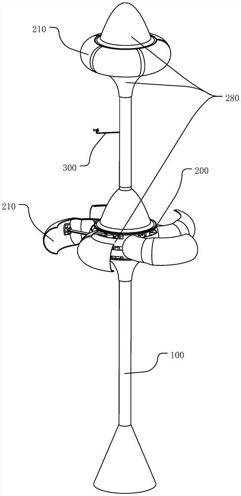
[0045] figure 1 It is a schematic diagram of a power gen...


PUM


Abstract

The present application discloses a power generation device to completely solve the problem of overspeed rotation of the generator set. The power generation device includes: a column; at least one generator set on the column, the generator set includes a bracket, blades connected to the bracket, and rotated by the blades A generator for generating electricity; wherein, the generator set also includes an adjustment device on the bracket, which is used to move or rotate the blades to adjust the wind-receiving area of ​​the blades according to the magnitude of the wind speed. The wind power generation device can reduce the effective wind-receiving area to zero when the wind is too strong, improve the stability of the equipment and the applicability in changing environments, and prolong the service life of the equipment. The outer surface of the power generating device can be laid with solar panels, so that the device can collect wind energy and solar energy at the same time, realizing combined wind and solar power generation. The components of the generator set in the power generating device are directly or indirectly connected to the column through bearings, which are convenient to disassemble and assemble, popularize and apply, and have strong practicability.

Description

technical field [0001] The invention relates to the technical field of power generation equipment, in particular to a power generation device for wind energy and solar energy combined power generation. Background technique [0002] Wind turbine is a kind of power generation equipment that is both environmentally friendly and relatively low in power generation cost. At present, the horizontal axis propeller wind turbine is widely used. The rotating shaft of this type of wind generator is set horizontally, and the blades are driven by the wind to convert the wind into electrical energy. However, the structure of the control system of this type of wind generator is complex and technical The difficulty is high, large-scale units have high requirements on materials, and the manufacturing cost is very high, which is not conducive to the popularization and wide application of wind power generation. Compared with the defects of horizontal-axis wind turbines, vertical-axis wind turb...

Claims


Application Information

Patent Timeline
Patent Type & Authority Patents(China)
IPC IPC(8): F03D9/25F03D3/02F03D3/06F03D7/06H02S10/12
CPCF03D9/25F03D9/007F03D3/02F03D3/062F03D7/06H02S10/12Y02E10/50Y02E10/74H02S20/30H02S30/20Y02E10/72Y02E10/728F05B2240/202F05B2240/2021F05B2220/708F05B2270/32F03D13/20F03D15/00F03D17/00F03D1/0641F03D3/061F03D7/042F05B2240/301F05B2240/302F05B2260/4031F05B2260/406F05B2260/602F05B2270/1011F05B2270/604F05B2280/107
Inventor 靳军
Owner 靳军
Why Eureka
Try Eureka