Chip-collecting device

A technology for recycling devices and swarf, which is applied in maintenance and safety accessories, electrode maintenance, electrode characteristics, etc., can solve problems such as increased load on the drive unit, device failure, etc., and achieves the effect of high swarf recycling capacity

Inactive Publication Date: 2019-12-06
KYOKUTOH
View PDF10 Cites 0 Cited by
  • Summary
  • Abstract
  • Description
  • Claims
  • Application Information

AI Technical Summary

Problems solved by technology

[0003] However, if the chips generated when cutting the tip of the electrode tip with the tip dresser adhere to the driving part of the device, the load on the driving part will increase, and in the worst case, the device may break down. Recycling of swarf immediately after generation

Method used


Image

  • Chip-collecting device
  • Chip-collecting device
  • Chip-collecting device

Examples


Embodiment Construction

[0033] Hereinafter, embodiments of the present invention will be described in detail with reference to the drawings. It should be noted that the following description of the preferred embodiments is exemplary only in nature.

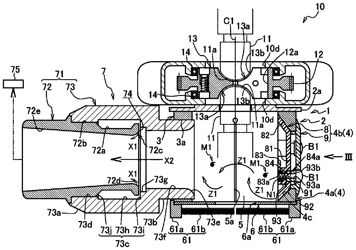
[0034] figure 1 A tip dresser 10 to which the chip recovery device 1 according to the embodiment of the present invention is mounted is shown. Such as figure 2 As shown, the swarf recovery device 1 is used to recover swarf M1 generated when the tips 11 a of a pair of electrode tips 11 attached to a spot welding torch are respectively cut by the tip dresser 10 .

[0035] Such as figure 1 As shown, the above-mentioned electrode tip dresser 10 includes: a substantially cylindrical motor casing part 10a with the cylinder centerline direction facing the up and down direction; A plate-shaped gear case part 10b; and a shock absorbing mechanism part 10c attached to the back of the motor case part 10a to absorb the impact applied to the motor case part 10a. ...


PUM


Abstract

The present invention provides a chip-collecting device. The chip-collecting device (1) collects chips (M1) generated when cutting electrode tips (11) with a tip dresser (10). A cover case (2), whichis fixed to the tip dresser (10), has a rectangular plate-shaped first side wall (3) and second side wall (4) that face each other in the horizontal direction. An air suction tool (7) is connected tothe first side wall (3). An air introduction hole (15) is formed in the lower part of the second side wall (4). The air introduction hole (15) is inclined so that proceeding towards the interior of the cover case (2), the hole gradually approaches the inner surface and inner bottom surface of the cover case (2).

Description

technical field [0001] The present invention relates to a swarf recovery device for recovering swarf generated by the cutting operation when cutting the tip of a spot welding electrode tip with a tip dresser. Background technique [0002] Conventionally, it is known that an oxide film adheres to the tip of an electrode tip during repeated welding operations in spot welding. Furthermore, if spot welding is performed directly with the oxide film adhering to the tip of the electrode tip, the quality of the welded part will deteriorate. Therefore, the tip of the electrode tip is usually cut regularly with a tip dresser to remove the oxide film. [0003] However, if the chips generated when cutting the tip of the electrode tip with the tip dresser adhere to the driving part of the device, the load on the driving part will increase, and in the worst case, the device may break down. Chips are recovered immediately after they are generated. [0004] In order to solve this problem,...

Claims


Application Information

Patent Timeline
Patent Type & Authority Applications(China)
IPC IPC(8): B23Q11/00B23K11/30
CPCB23K11/3063B23Q11/0046B23Q11/00
Inventor 中嶋弘太郎
Owner KYOKUTOH
Why Eureka
Try Eureka