A bearing provided with a cage mechanism

A cage and bearing technology, applied in the field of bearings, can solve the problems of general wear resistance, lower friction coefficient, and inability to prevent impurities reasonably and effectively, and achieve improved strength and wear resistance, simple and compact structure, and long-term use Effect

Active Publication Date: 2020-12-11
DOUBLE COIN GRP JIANGSU TIRE
View PDF16 Cites 0 Cited by
  • Summary
  • Abstract
  • Description
  • Claims
  • Application Information

AI Technical Summary

Problems solved by technology

Its main function is to support the mechanical rotating body, reduce the friction coefficient during its movement, and ensure its rotation accuracy. my country's bearing industry is developing rapidly. The variety of bearings is increasing from few to many, and the product quality and technical level are from low to high. The scale of the industry From small to large, a professional production system with basically complete product categories and a relatively reasonable production layout has been formed. Bearings are widely used in the existing market. Among them, bearings mainly include structural combinations such as inner rings, outer rings, balls and cages. As a result, the cages in the existing bearings are mostly integral structures, which is not conducive to the disassembly of the cages and the replacement of damaged balls in the later stage. The wear of the balls in the later stage, the structure of the balls is relatively simple, and the wear resistance is average

Method used


Image

  • A bearing provided with a cage mechanism
  • A bearing provided with a cage mechanism
  • A bearing provided with a cage mechanism

Examples


Embodiment Construction

[0019] The following will clearly and completely describe the technical solutions in the embodiments of the present invention with reference to the accompanying drawings in the embodiments of the present invention. Obviously, the described embodiments are only some, not all, embodiments of the present invention. Based on the embodiments of the present invention, all other embodiments obtained by persons of ordinary skill in the art without making creative efforts belong to the protection scope of the present invention.

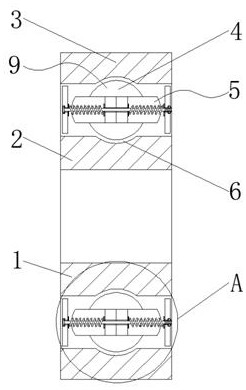
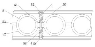
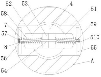
[0020] see Figure 1-4 , the present invention provides a technical solution: a bearing with a cage mechanism, including a bearing main body 1, a bearing inner ring 2, a bearing outer ring 3, balls 4, a cage assembly 5, rolling grooves 6, gaskets 7, Countersunk hole 8 and ball outer layer assembly 9, bearing inner ring 2 is arranged inside bearing main body 1, bearing outer ring 3 is arranged outside bearing inner ring 2, bearing outer ring 3 and bearing inner...


PUM


Abstract

The invention discloses a bearing with a retainer mechanism. The bearing comprises a bearing main body, a bearing inner ring, a bearing outer ring, balls, a retainer assembly, a rolling groove, a gasket, a counterbore and a ball outer layer assembly, wherein the bearing inner ring is arranged in the bearing main body; the bearing body is provided with the bearing outer ring located outside the bearing inner ring; the balls are distributed and clamped on the inner wall between the bearing outer ring and the bearing inner ring; the retainer assembly is arranged on the outer walls, located on thetwo sides of the balls, of the bearing body; and a first splicing frame is arranged on the inner wall, located on one sides of the balls, of the bearing body. The bearing is simple and compact in structure, the retainer assembly is arranged on the basis of a traditional bearing, the structure is beneficial to later disassembling of the retainer and later replacement of the balls, a dust blockingring is fixedly installed to achieve a good dustproof effect on the bearing, later storage of lubricating grease in the bearing is also facilitated, and later abrasion to the balls is reduced.

Description

technical field [0001] The invention relates to the technical field of bearings, in particular to a bearing provided with a cage mechanism. Background technique [0002] Bearings are an important part of contemporary mechanical equipment. Its main function is to support the mechanical rotating body, reduce the friction coefficient during its movement, and ensure its rotation accuracy. my country's bearing industry is developing rapidly. The variety of bearings is increasing from few to many, and the product quality and technical level are from low to high. The scale of the industry From small to large, a professional production system with basically complete product categories and a relatively reasonable production layout has been formed. Bearings are widely used in the existing market. Among them, bearings mainly include structural combinations such as inner rings, outer rings, balls and cages. As a result, the cages in the existing bearings are mostly integral structures, w...

Claims


Application Information

Patent Timeline
Patent Type & Authority Patents(China)
IPC IPC(8): F16C19/02F16C33/32F16C33/38F16C33/62F16C33/78
CPCF16C19/02F16C33/32F16C33/3862F16C33/62F16C33/7806F16C33/7893
Inventor 石太平
Owner DOUBLE COIN GRP JIANGSU TIRE
Why Eureka
Try Eureka