
Steel hoop machining feeding control system and control method based on three-dimensional visual guidance

A technology of three-dimensional vision and control method, which is applied in metal processing equipment, manufacturing tools, manipulators, etc., can solve problems such as the inability to realize three-dimensional data calculation, and achieve the effect of speeding up the feeding cycle

Pending Publication Date: 2019-11-29
HENAN ALSONTECH INTELLIGENT TECH CO LTD
View PDF2 Cites 15 Cited by
  • Summary
  • Abstract
  • Description
  • Claims
  • Application Information

AI Technical Summary

Problems solved by technology

The three-dimensional coordinates of the binocular camera positioning clutch used in the above method depend on the image quality of the characteristic holes captured by the camera, and high-quality lighting needs to be provided by the light source. At the same time, it is only suitable for the positioning of a single workpiece. When there are interfering characteristic holes in the field of view , it will not be possible to solve the three-dimensional data

Method used


Image

  • Steel hoop machining feeding control system and control method based on three-dimensional visual guidance
  • Steel hoop machining feeding control system and control method based on three-dimensional visual guidance
  • Steel hoop machining feeding control system and control method based on three-dimensional visual guidance

Examples


Embodiment Construction

[0041]In order to facilitate the understanding of the present invention, the present invention will be described in more detail below in conjunction with the accompanying drawings and specific embodiments. Preferred embodiments of the invention are shown in the accompanying drawings. However, the present invention can be implemented in many different forms and is not limited to the embodiments described in this specification. On the contrary, these embodiments are provided to make the understanding of the disclosure of the present invention more thorough and comprehensive.

[0042] It should be noted that, unless otherwise defined, all technical and scientific terms used in this specification have the same meaning as commonly understood by those skilled in the technical field of the present invention. Terms used in the description of the present invention are only for the purpose of describing specific embodiments, and are not used to limit the present invention. The term "a...


PUM


Abstract

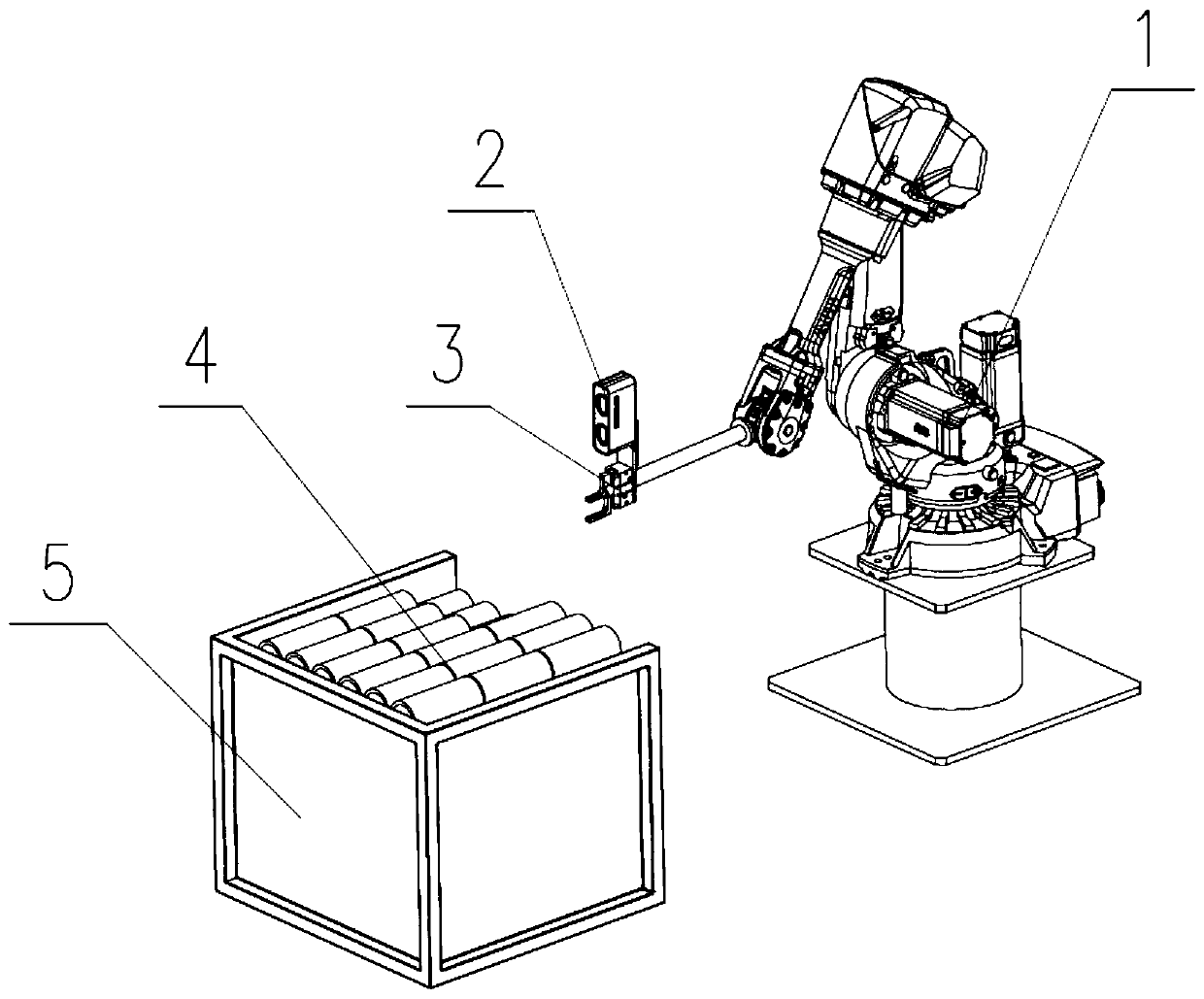
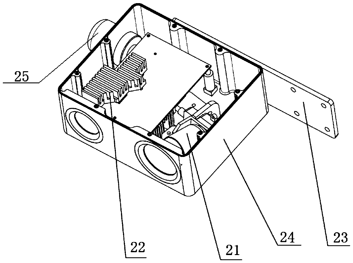
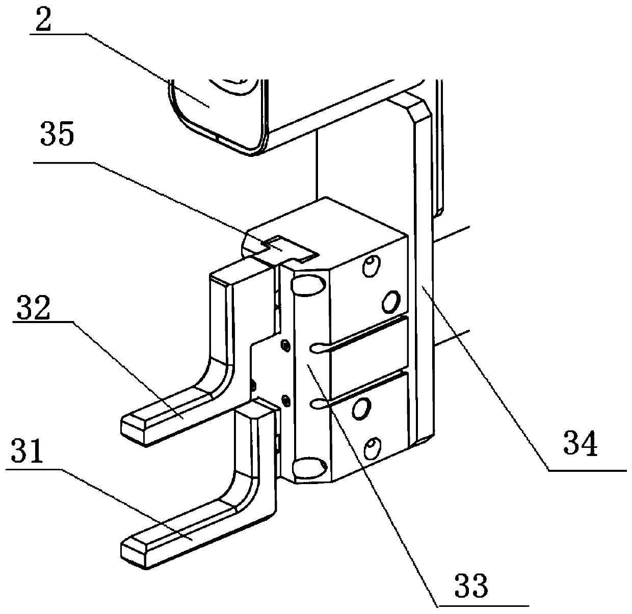
The invention discloses a steel hoop machining feeding control system and control method based on three-dimensional visual guidance. The system comprises a controller, a mechanical arm and a three-dimensional sensor, wherein the mechanical arm and the three-dimensional sensor are in control connection with the controller. A clamp used for grabbing steel hoops is arranged at the tail end of the mechanical arm. The three-dimensional sensor is arranged at the tail end of the mechanical arm and used for carrying out image and three-dimensional data scanning on the to-be-grabbed steel hoops and transmitting scanned data to the controller. The controller controls the clamp connected with the tail end of the mechanical arm to act so as to grab the steel hoops according to the scanned data of thethree-dimensional sensor. The three-dimensional sensor is used for shooting two-dimensional images and three-dimensional data of the steel hoops, a one-one mapping relation is built between the two-dimensional images and the three-dimensional data, the pose of the mechanical arm for grabbing workpieces is solved on this basis, rationality of steel hoop grabbing is judged, and then the industrial mechanical arm is guided to grab the steel hoops, and therefore feeding machining on the steel hoops placed in a frame is achieved; and automation of steel hoop thread machining is achieved so as to improve production efficiency and save manual cost.

Description

technical field [0001] The invention belongs to the field of automatic control of steel hoop processing, and in particular relates to a three-dimensional vision-guided steel hoop processing feeding control system and control method. Background technique [0002] With the rapid development of industrial automation, the application of industrial manipulators in large-scale steel plant parts processing is becoming more and more common. However, for most steel plant part processing application scenarios using industrial manipulators, manual teaching or offline programming is required to Planning the working path of the manipulator, this highly structured working mode strictly limits the flexibility and intelligence of industrial manipulators, and cannot meet the needs of flexible production. [0003] In the production process of steel hoops produced by the pouring process in the steel factory, the current production method is still to transport the whole frame of steel hoops to ...

Claims


Application Information

Patent Timeline
IPC IPC(8): B25J13/00B25J13/08B23G11/00
CPCB25J13/00B25J13/08B23G11/00Y02P90/02
Inventor 苗庆伟张卓辉王志飞
Owner HENAN ALSONTECH INTELLIGENT TECH CO LTD
Learn More