Optical fiber connector with lock catch
A technology of optical fiber connectors and optical fiber adapters, applied in the field of optical fiber equipment, can solve problems such as communication disconnection, and achieve the effect of ensuring connection stability and reliability
- Summary
- Abstract
- Description
- Claims
- Application Information
AI Technical Summary
Problems solved by technology
Method used
Image

Examples
Embodiment 1
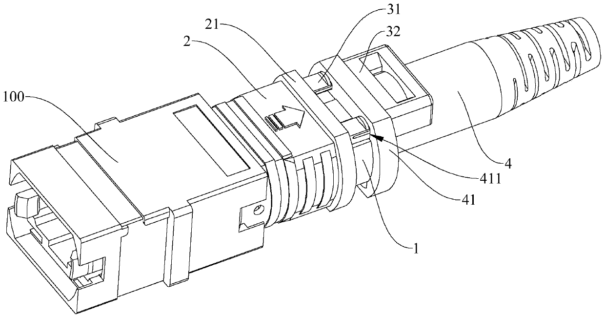
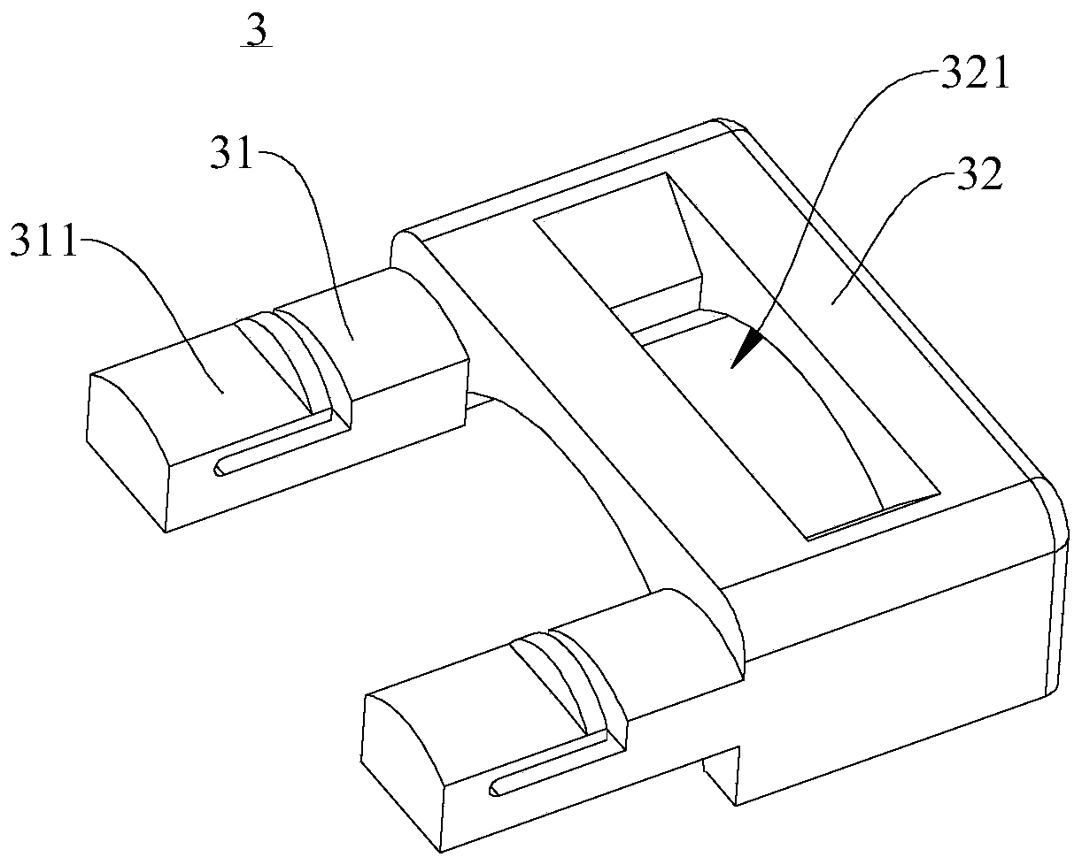
[0058] Such as Figure 1-Figure 2 As shown, the fiber optic connector with a lock in this embodiment includes a body 1, an outer frame 2, a lock 3 and a boot 4, the body 1 is inserted into the optical fiber adapter 100, and the outer frame 2 is slidably fitted on the body 1 Above, the outer frame 2 is provided with an annular protrusion 21. The outer frame 2 has a locked position and a released position. In the locked position, the outer frame 2 locks the body 1 on the optical fiber adapter 100. In the released position, the outer frame 2 Release body 1. The tail cover 4 is connected to the body 1, and the tail cover 4 is spaced from the outer frame 2. The tail cover 4 includes a tail frame cover 41, which is fitted on the body 1. The tail frame cover 41 is provided with a first matching hole 411 , the lock 3 includes a lock 31, the lock 31 includes two first protrusions 31 and a second protrusion 32, and one end of each first protrusion 31 is formed with an elastic piece 311...
Embodiment 2
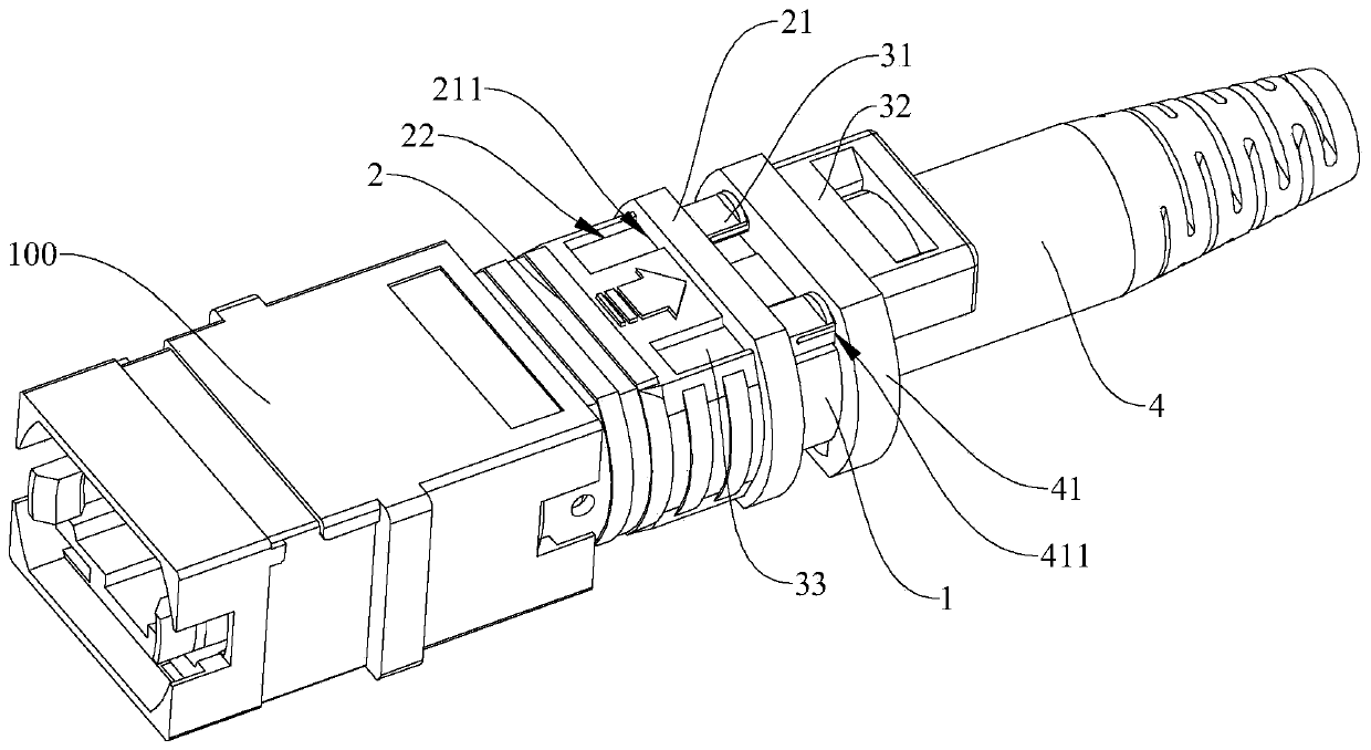
[0060] Such as Figure 3-Figure 5 As shown, the fiber optic connector with a lock in this embodiment includes a body 1, an outer frame 2, a lock 3 and a boot 4, the body 1 is inserted into the optical fiber adapter 100, and the outer frame 2 is slidably fitted on the body 1 Above, the outer frame 2 is provided with an annular protrusion 21, and the annular protrusion 21 is provided with a second matching hole 211, and the second matching hole 211 is a through hole, and the outer frame 2 is provided with a corresponding setting for the second matching hole 211. The mating groove 22. The outer frame 2 has a locked position and a released position. In the locked position, the outer frame 2 locks the main body 1 on the optical fiber adapter 100 . In the released position, the outer frame 2 releases the main body 1 . The tail cover 4 is connected to the body 1, and the tail cover 4 is spaced from the outer frame 2. The tail cover 4 includes a tail frame cover 41, which is fitted o...
Embodiment 3
[0062] Such as Figure 6 As shown, the fiber optic connector with a lock in this embodiment includes a body 1, an outer frame 2, a lock 3 and a boot 4, the body 1 is inserted into the optical fiber adapter 100, and the outer frame 2 is slidably fitted on the body 1 Above, the outer frame 2 is provided with an annular protrusion 21. The outer frame 2 has a locked position and a released position. In the locked position, the outer frame 2 locks the body 1 on the optical fiber adapter 100. In the released position, the outer frame 2 Release body 1. The tail cover 4 is connected to the body 1, and the tail cover 4 is spaced from the outer frame 2. The tail cover 4 includes a tail frame cover 41, and the tail frame cover 41 is fitted on the body 1. The lock buckle 3 is formed as an elastic body. One end abuts against the tail frame sleeve 41 , and the other end abuts against the annular protrusion 21 .
PUM
 Abstract
Description
Claims
Application Information
 - R&D
- Intellectual Property
- Life Sciences
- Materials
- Tech Scout
- Unparalleled Data Quality
- Higher Quality Content
- 60% Fewer Hallucinations
Browse by: Latest US Patents, China's latest patents, Technical Efficacy Thesaurus, Application Domain, Technology Topic, Popular Technical Reports.
© 2025 PatSnap. All rights reserved.Legal|Privacy policy|Modern Slavery Act Transparency Statement|Sitemap|About US| Contact US: help@patsnap.com