Vision radar

A radar and visual technology, applied in the field of visual radar, can solve the problems of low accuracy of visual radar, cumbersome installation and disassembly, easy to be interfered, etc., to achieve the effect of enhancing convenience, delaying aging speed, and improving accuracy

Pending Publication Date: 2019-11-26
上海邺格工业自动化有限公司
View PDF0 Cites 0 Cited by
  • Summary
  • Abstract
  • Description
  • Claims
  • Application Information

AI Technical Summary

Problems solved by technology

[0007] The purpose of the present invention is to provide a visual radar to solve the problems of low accuracy, cumbersome installation and disassembly, and susceptibility to interference in the above-mentioned background technology.

Method used


Image

  • Vision radar
  • Vision radar
  • Vision radar

Examples


Embodiment Construction

[0026] The following will clearly and completely describe the technical solutions in the embodiments of the present invention with reference to the accompanying drawings in the embodiments of the present invention. Obviously, the described embodiments are only some, not all, embodiments of the present invention. Based on the embodiments of the present invention, all other embodiments obtained by persons of ordinary skill in the art without making creative efforts belong to the protection scope of the present invention.

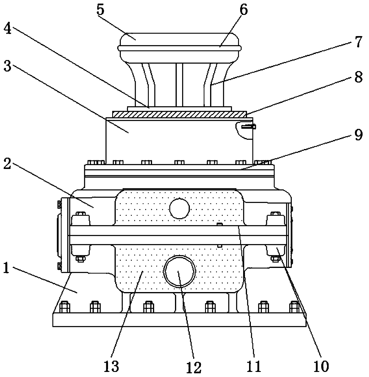
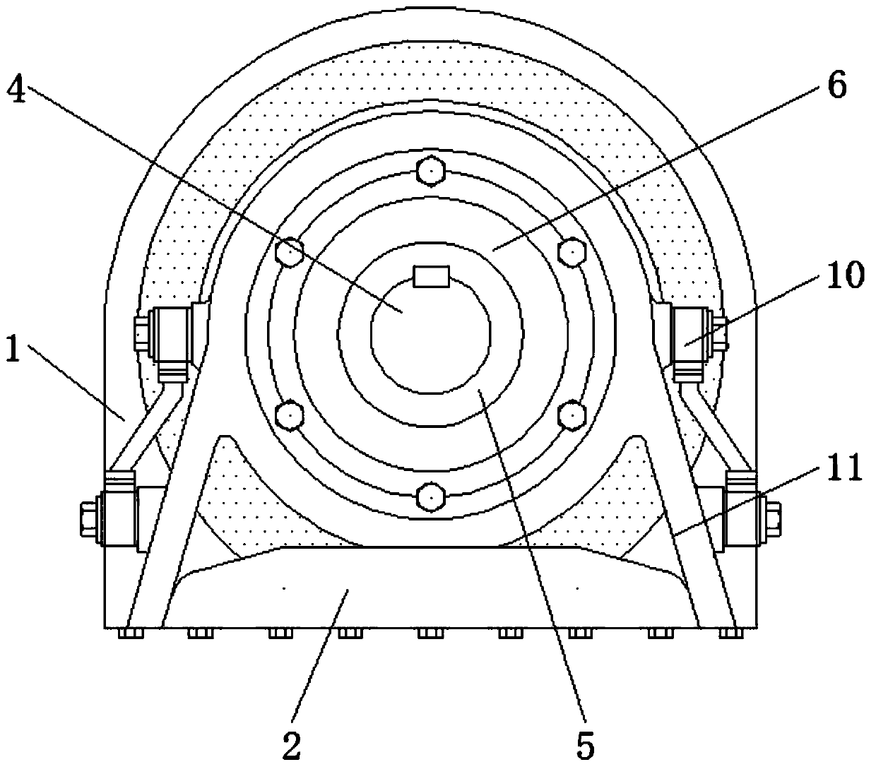
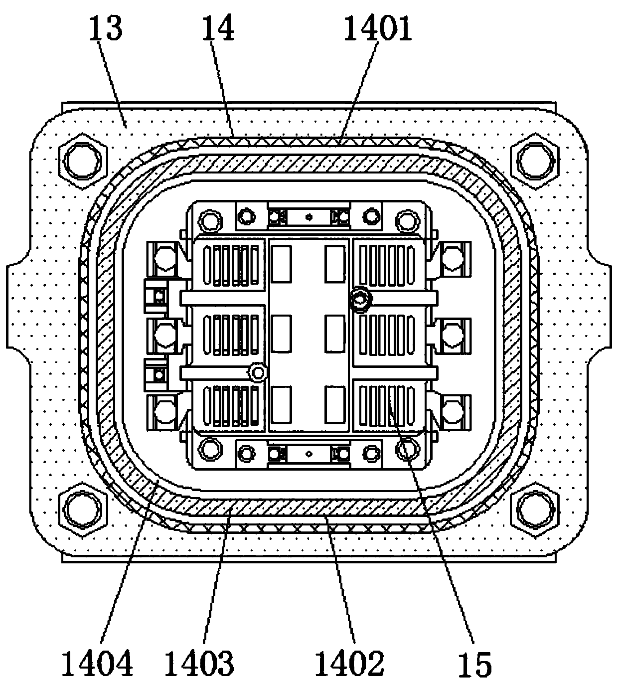
[0027] see Figure 1-4 , a kind of embodiment that the present invention provides: vision radar, comprises installation frame 1, fixed plate 2, motor 3, rotating shaft 4 and lubricating structure 8, and the top of mounting frame 1 is welded with fixed plate 2, fixed plate 2 and receiving platform 13 A movable frame 11 is installed at the connecting position, and both ends of the installation and removal bolts 10 are provided with installation and removal bolts...


PUM


Abstract

The invention discloses a vision radar which comprises a mounting frame, a fixation plate, a motor, a rotating shaft and a lubricating structure. The fixation plate is welded on the top of the mounting frame. The motor is arranged on the top of the fixation plate. The output end of the motor is provided with the rotating shaft through a coupling. A receiving platform is welded on the top of the mounting frame. An anti-interference structure is arranged inside the receiving platform. An ARM board is fixed inside the receiving platform on one side of the anti-interference structure. The output end of the ARM board and the input end of the motor are electrically connected. The lubricating structure sleeves one end of the rotating shaft. A high-definition camera is fixed on one end, which is far from the motor, of the rotating shaft. One end of the high-definition camera contacts the surface of the lubricating structure. According to the invention, the aging speed of the used vision radaris delayed; the use convenience of the vision radar is enhanced; and the use accuracy of the vision radar is improved.

Description

technical field [0001] The invention relates to the technical field of visual radar, in particular to visual radar. Background technique [0002] With the continuous development and progress of people's scientific and technological level, the common manual and multi-programs in life are gradually replaced. Among them, radar is widely used, but the high cost of laser radar makes it difficult to achieve universal application. At this time, the application of visual radar more important. [0003] There are many types of such visual radars on the market today, which can basically meet people's needs, but there are still some problems. The specific problems are as follows: [0004] (1) The long-term wear and tear of the traditional visual radar leads to jamming, which seriously affects the accuracy of the visual radar; [0005] (2) The installation and disassembly of the traditional visual radar is cumbersome, which greatly affects the practicability of the visual radar; [00...

Claims


Application Information

Patent Timeline
IPC IPC(8): G01S7/481
CPCG01S7/481
Inventor 高永辉王真王俊强
Owner 上海邺格工业自动化有限公司
Why Eureka
Try Eureka